Ok thanks, that was the query now: if it is the same then what is the significance of PDSCH antenna port 1000-1011?
Those are for DMRS for PDSCH.
Maximum 12 can be.
And have to be reused if 16 layers are used.
Yes thanks agree on it.
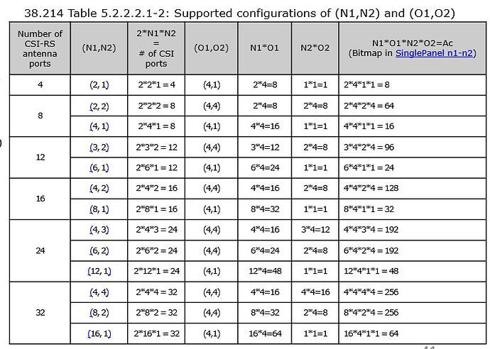
With maximum up to 32 CSI RS port we can have 128 beams with a maximum configuration of N1, N2 and O1 O2.
But as per transmission scheme 1 in 5G we can have a maximum layer of PDSCH is 8 only then what is the meaning of these many beams of CSI RS?
That is not right. 32 csi-rs ports do not mean 128 beams.
32 csi-rs ports are not related to number of beams.
csi-rs beams point in different direction so to cover the whole sector.
UE will report that it is able to decode csi-rs beams 3,22,19 and 7.
So gNodeB will schedule data only on those beams because other beams UE cannot decode.
Cannot decode other beams. Ue does not “see” other beams.
Yes, this table is correct but have not seen up to now networks with 32 csi-rs ports.
It would be too complex to handle I think for now.
Ok agree. For example, if we have 64 CSI beams configured now; these 64 beams transmitted on different SSB as 1 ssb = 4 csi rs beam so we need 16 SSB to have 64 CSI RS beams and gNB select 4 strongest beams to schedule user date on CSI RS beam.
Is this understanding is correct?
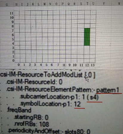
I have yet to see how UE is instructed about 64 csi-rs beams in time (frame, subframe, slot, symbols) and frequency (RE and RBs).
Yes I think Ericsson is supporting 32 port in mmWave.
Yes when csi-rs beams are enabled it works like this.
Just keep in mind that those 4 csi-rs beams do not have to be from same SSB.
Thanks, yes that will create interference if we use 4 csi rs from same SSB.
If you can share a log or how csi-rs beams are configured in RRC message it would be great.
I heard it, but i don’t have the logs. I’ll try to get it.
I have yet to see how UE is instructed about 64 csi-rs beams in time (frame, subframe, slot, symbols) and frequency (RE and RBs) in RRC messages for 64 csi-rs beams.
When I will see this I can conclude that csi-rs beams are enabled.
Not before this.
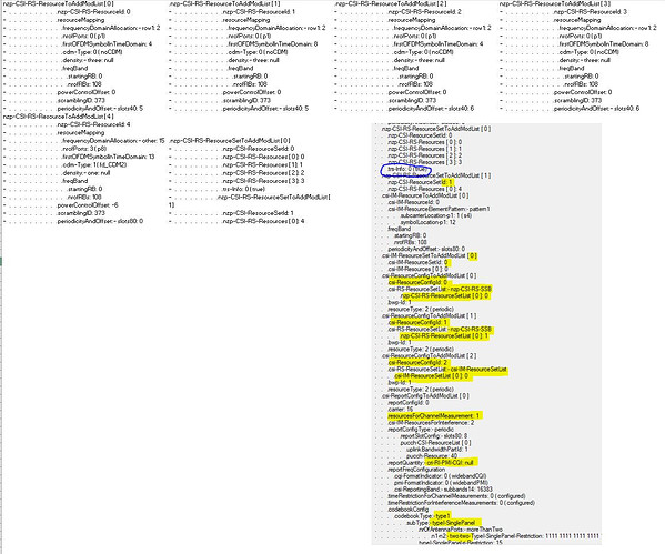
This is an example of nzp csi-rs ports configured:
-                     csi-MeasConfig:- setup
-                           nzp-CSI-RS-ResourceToAddModList [ 0 ]
-                              nzp-CSI-RS-ResourceId: 0
-                              resourceMapping
-                                 frequencyDomainAllocation:- row1: 2
-                                 nrofPorts: 0 ( p1)
-                                 firstOFDMSymbolInTimeDomain: 4
-                                 cdm-Type: 0 ( noCDM)
-                                 density:- three: null
-                                 freqBand
-                                    startingRB: 0
-                                    nrofRBs: 108
-                              powerControlOffset: 0
-                              scramblingID: 373
-                              periodicityAndOffset:- slots40: 5
-                           nzp-CSI-RS-ResourceToAddModList [ 1 ]
-                              nzp-CSI-RS-ResourceId: 1
-                              resourceMapping
-                                 frequencyDomainAllocation:- row1: 2
-                                 nrofPorts: 0 ( p1)
-                                 firstOFDMSymbolInTimeDomain: 8
-                                 cdm-Type: 0 ( noCDM)
-                                 density:- three: null
-                                 freqBand
-                                    startingRB: 0
-                                    nrofRBs: 108
-                              powerControlOffset: 0
-                              scramblingID: 373
-                              periodicityAndOffset:- slots40: 5
-                           nzp-CSI-RS-ResourceToAddModList [ 2 ]
-                              nzp-CSI-RS-ResourceId: 2
-                              resourceMapping
-                                 frequencyDomainAllocation:- row1: 2
-                                 nrofPorts: 0 ( p1)
-                                 firstOFDMSymbolInTimeDomain: 4
-                                 cdm-Type: 0 ( noCDM)
-                                 density:- three: null
-                                 freqBand
-                                    startingRB: 0
-                                    nrofRBs: 108
-                              powerControlOffset: 0
-                              scramblingID: 373
-                              periodicityAndOffset:- slots40: 6
-                           nzp-CSI-RS-ResourceToAddModList [ 3 ]
-                              nzp-CSI-RS-ResourceId: 3
-                              resourceMapping
-                                 frequencyDomainAllocation:- row1: 2
-                                 nrofPorts: 0 ( p1)
-                                 firstOFDMSymbolInTimeDomain: 8
-                                 cdm-Type: 0 ( noCDM)
-                                 density:- three: null
-                                 freqBand
-                                    startingRB: 0
-                                    nrofRBs: 108
-                              powerControlOffset: 0
-                              scramblingID: 373
-                              periodicityAndOffset:- slots40: 6
-                           nzp-CSI-RS-ResourceToAddModList [ 4 ]
-                              nzp-CSI-RS-ResourceId: 4
-                              resourceMapping
-                                 frequencyDomainAllocation:- other: 15
-                                 nrofPorts: 3 ( p8)
-                                 firstOFDMSymbolInTimeDomain: 13
-                                 cdm-Type: 1 ( fd_CDM2)
-                                 density:- one: null
-                                 freqBand
-                                    startingRB: 0
-                                    nrofRBs: 108
-                              powerControlOffset: -6
-                              scramblingID: 373
-                              periodicityAndOffset:- slots80: 0
-                           nzp-CSI-RS-ResourceSetToAddModList [ 0 ]
-                              nzp-CSI-ResourceSetId: 0
-                              nzp-CSI-RS-Resources [ 0 ]: 0
-                              nzp-CSI-RS-Resources [ 1 ]: 1
-                              nzp-CSI-RS-Resources [ 2 ]: 2
-                              nzp-CSI-RS-Resources [ 3 ]: 3
-                              trs-Info: 0 ( true)
-                           nzp-CSI-RS-ResourceSetToAddModList [ 1 ]
-                              nzp-CSI-ResourceSetId: 1
-                              nzp-CSI-RS-Resources [ 0 ]: 4
As you see resoruceid4 is for 8 csi-rs ports.
But those are not csi-rs beams.
Those are csi-rs ports
To my understanding we should see inside RRC messages TCI and QCL IEs in order to conclude that csi-rs beams are enabled.
Like in this example: (message is capped, it is much longer)
-                     csi-MeasConfig:- setup
-                           nzp-CSI-RS-ResourceToAddModList [ 0 ]
-                              nzp-CSI-RS-ResourceId: 0
-                              resourceMapping
-                                 frequencyDomainAllocation:- row1: 2
-                                 nrofPorts: 0 ( p1)
-                                 firstOFDMSymbolInTimeDomain: 4
-                                 cdm-Type: 0 ( noCDM)
-                                 density:- three: null
-                                 freqBand
-                                    startingRB: 0
-                                    nrofRBs: 108
-                              powerControlOffset: 0
-                              scramblingID: 373
-                              periodicityAndOffset:- slots40: 5
-                           nzp-CSI-RS-ResourceToAddModList [ 1 ]
-                              nzp-CSI-RS-ResourceId: 1
-                              resourceMapping
-                                 frequencyDomainAllocation:- row1: 2
-                                 nrofPorts: 0 ( p1)
-                                 firstOFDMSymbolInTimeDomain: 8
-                                 cdm-Type: 0 ( noCDM)
-                                 density:- three: null
-                                 freqBand
-                                    startingRB: 0
-                                    nrofRBs: 108
-                              powerControlOffset: 0
-                              scramblingID: 373
-                              periodicityAndOffset:- slots40: 5
-                           nzp-CSI-RS-ResourceToAddModList [ 2 ]
-                              nzp-CSI-RS-ResourceId: 2
-                              resourceMapping
-                                 frequencyDomainAllocation:- row1: 2
-                                 nrofPorts: 0 ( p1)
-                                 firstOFDMSymbolInTimeDomain: 4
-                                 cdm-Type: 0 ( noCDM)
-                                 density:- three: null
-                                 freqBand
-                                    startingRB: 0
-                                    nrofRBs: 108
-                              powerControlOffset: 0
-                              scramblingID: 373
-                              periodicityAndOffset:- slots40: 6
-                           nzp-CSI-RS-ResourceToAddModList [ 3 ]
-                              nzp-CSI-RS-ResourceId: 3
-                              resourceMapping
-                                 frequencyDomainAllocation:- row1: 2
-                                 nrofPorts: 0 ( p1)
-                                 firstOFDMSymbolInTimeDomain: 8
-                                 cdm-Type: 0 ( noCDM)
-                                 density:- three: null
-                                 freqBand
-                                    startingRB: 0
-                                    nrofRBs: 108
-                              powerControlOffset: 0
-                              scramblingID: 373
-                              periodicityAndOffset:- slots40: 6
-                           nzp-CSI-RS-ResourceToAddModList [ 4 ]
-                              nzp-CSI-RS-ResourceId: 4
-                              resourceMapping
-                                 frequencyDomainAllocation:- other: 15
-                                 nrofPorts: 3 ( p8)
-                                 firstOFDMSymbolInTimeDomain: 13
-                                 cdm-Type: 1 ( fd_CDM2)
-                                 density:- one: null
-                                 freqBand
-                                    startingRB: 0
-                                    nrofRBs: 108
-                              powerControlOffset: -6
-                              scramblingID: 373
-                              periodicityAndOffset:- slots80: 0
-                           nzp-CSI-RS-ResourceSetToAddModList [ 0 ]
-                              nzp-CSI-ResourceSetId: 0
-                              nzp-CSI-RS-Resources [ 0 ]: 0
-                              nzp-CSI-RS-Resources [ 1 ]: 1
-                              nzp-CSI-RS-Resources [ 2 ]: 2
-                              nzp-CSI-RS-Resources [ 3 ]: 3
-                              trs-Info: 0 ( true)
-                           nzp-CSI-RS-ResourceSetToAddModList [ 1 ]
-                              nzp-CSI-ResourceSetId: 1
-                              nzp-CSI-RS-Resources [ 0 ]: 4
Please anyone if it has a UE log to see how UE is instructed about when/how csi-rs beams are transmitted in freq/time/space, I would like to see it.
For FR1, there are max of 8 SSB beams.
Since 1 SSB beam = 4 CSI RS beams, hence 32 CSI RS beam will require for 8 SSS beams.
In my network, we have configured 4 CSI RS resources per PRB i.e. 4 Beams.
So how the gNB will radiate 32 CSI RS beams…
In Huawei, 64 csi-rs beams. 4 for each ssb ( ssb = 16 in mmWave)
Can you paste here how those resources nzp-csi-rs are configured?
Is trs-info = true for them?
If it’s like this then those are trs-info for tracking ( fine tuning of time and frequency).
Check trs-info = true. If its is present in rrc reconfig message.
" ‘trs-Info’ flag: this is used to indicate that the CSI Reference Signal Resource
Set is to be used as a Tracking Reference Signal (TRS), i.e. it is to be used for fine tuning of time and frequency synchronisation. "
TRS is also used for beam management procedure.
So this might be the csi-rs beams we are looking after.
It is normally used for decoding higher modulation rate.
Normally, trs periodicity of 20 ms and CSI RS of 40 ms is used.
For FR1, SCS 30 KHz.

Aren’t those for interference management?
Yes, one of the use case of CSI RS.
We should look for nzp-csi-rs.

