Beamforming in 5G: The Technology that Drives Network Efficiency
As mobile networks evolve and the demand for high-quality connectivity continues to grow, 5G has introduced several technological innovations. One of the most significant advancements is Beamforming, an advanced technique that allows the signal to be directed where it’s needed most, improving efficiency and coverage. This article will explain what Beamforming is, its benefits, its advantages over LTE, and how it can be monitored in practice through network commands.
What is Beamforming in 5G?
Beamforming is a technology that allows 5G base stations to direct radio signals to specific regions rather than broadcasting them equally in all directions as in previous mobile technologies. It uses multiple antennas to create focused signal beams, enabling more efficient transmission and better use of radio spectrum.
By focusing signals in areas with the greatest need for resources, such as densely populated regions or areas with many active users, Beamforming improves network coverage and capacity. It also helps avoid signal waste in areas where there is no demand, making the network more efficient.
Benefits of Beamforming
-
Targeted Coverage and Signal Efficiency: Beamforming allows signals to be sent directly to users or areas with higher demand, resulting in less interference and a stronger, more stable signal for connected devices.
-
Better Spectrum Utilization: By concentrating the signal where it’s needed most, Beamforming improves radio spectrum utilization, reducing resource wastage in low-demand areas.
-
Increased Network Capacity: By directing signals to high-demand areas, Beamforming enables more devices to connect simultaneously without compromising connection quality.
-
Reduced Interference: Focusing signals on specific areas minimizes interference with other cells and users, improving the overall user experience.
Beamforming Gains in 5G Compared to LTE
While Beamforming was already used in LTE (4G) networks, it was more limited. In 5G, this technology is significantly enhanced due to the use of Massive MIMO (Multiple Input, Multiple Output) antennas and higher frequencies, which allow for greater signal precision. Compared to LTE, Beamforming in 5G offers:
- Greater precision in directing signals, especially in dense urban environments.
- Better support for high frequencies, such as millimeter waves, which are crucial for 5G but require more accurate signal control due to their reduced propagation range.
- Ability to handle more simultaneous users, ensuring high-quality connectivity even in areas with large crowds, such as events or commercial zones.
Monitoring Command: shget CommonBeamforming coverageShape|usedCoverageShape
To check Beamforming configurations in a 5G network, you can use the following command:
shget CommonBeamforming coverageShape|usedCoverageShape
This command is used to display the coverage shapes that are currently being used and the ones supported by the network’s cells. The coverage shape defines the shape of the signal coverage beam in a specific cell.
Command Breakdown:
- CommonBeamforming: Refers to the common beamforming functionality in 5G networks.
- coverageShape: Displays the coverage shape supported by the cell.
- usedCoverageShape: Shows the currently utilized coverage shape.
Running this command provides a list of cells (NRSectorCarrier) and the corresponding coverage shape information.
Example Output and Analysis
=================================================================================================================
MO                                          coverageShape supportedCoverageShapes                     usedCoverageShape
=================================================================================================================
NRSectorCarrier=5S###11,CommonBeamforming=1 1 (MACRO_1)   i[3] = 1 2 3 (MACRO_1 HIGHRISE_1 HOTSPOT_1) 1 (MACRO_1)
NRSectorCarrier=5S###12,CommonBeamforming=1 1 (MACRO_1)   i[3] = 1 2 3 (MACRO_1 HIGHRISE_1 HOTSPOT_1) 1 (MACRO_1)
NRSectorCarrier=5S###13,CommonBeamforming=1 1 (MACRO_1)   i[3] = 1 2 3 (MACRO_1 HIGHRISE_1 HOTSPOT_1) 1 (MACRO_1)
=================================================================================================================
Total: 3 MOs
Output Details:
- MO (Managed Object): Refers to the cell (NRSectorCarrier) being monitored.
- coverageShape: The current coverage shape being used by the cell. In this example, all cells are using the MACRO_1 coverage shape, suitable for large areas.
- supportedCoverageShapes: The coverage shapes that the cell supports. In this case, the cells support three shapes:
- MACRO_1: For broad coverage in open areas.
- HIGHRISE_1: Optimized for high-rise buildings.
- HOTSPOT_1: For areas with high user density.
- usedCoverageShape: The coverage shape currently in use, which in this example is MACRO_1.
The output shows that, although the cells support multiple coverage shapes (including for high-density areas and buildings), they are currently using the MACRO_1 shape, the standard for large areas. This command is essential for adjusting the coverage strategy, allowing operators to identify whether the coverage shape in use is optimal for the given scenario.
Practical application:
M###1_##> shget CommonBeamforming coverageShape|usedCoverageShape
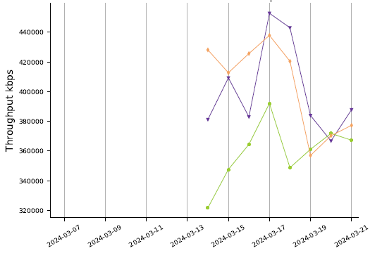
DL MAC DRB THROUGHPUT

Conclusion
Beamforming is a key enabler of 5G network efficiency, allowing signals to be directed to high-demand areas and optimizing coverage and resource use. Compared to LTE, Beamforming in 5G offers greater precision, better support for higher frequencies, and improved network capacity. By using commands like shget CommonBeamforming coverageShape|usedCoverageShape, operators can monitor and fine-tune beamforming configurations in practice, ensuring that network coverage and performance are optimized for the needs of each location.
LinkedIn (in Portuguese): ![]()
