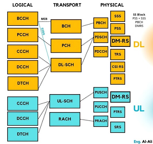
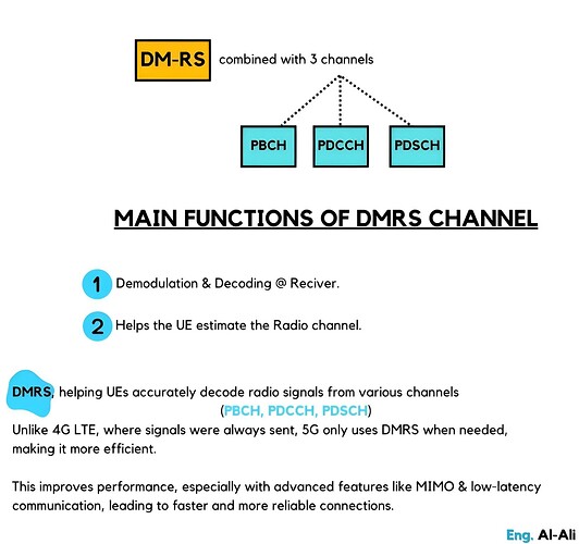
DMRS is present in both DL and UL serves similar functions, primarily assisting with channel estimation. It is always transmitted Combined with 3 physical channels PDSCH, PDCCH, PBCH, never transmitted independently.
In LTE, there was a similar RS called the CRS which was transmitted continuously, even when not needed. However, in 5G, reducing unnecessary signaling is a key focus. As a result, DMRS is only transmitted when needed
DMRS for PBCH
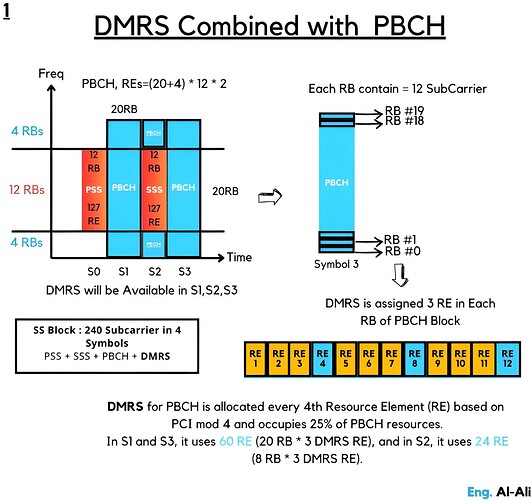
DMRS helps the UE estimate the radio channel for demodulating & decoding PBCH &MIB
DMRS is transmitted from the gNB using antenna port 4000.
DMRS in PBCH & it is part of the SS Block, occupies symbols 1, 2, & 3.
occupies every 4th RE, using 25% of PBCH resources.
Example of SSB:
In Symbols 1 and 3, DMRS occupies 60 REs
In Symbol 2, DMRS occupies 24 REs.
Note: Resource Block consists of 12 subcarriers in the frequency domain, Resource Element represents a single subcarrier containing one symbol.
Each RB consists of 12 REs (one per subcarrier).
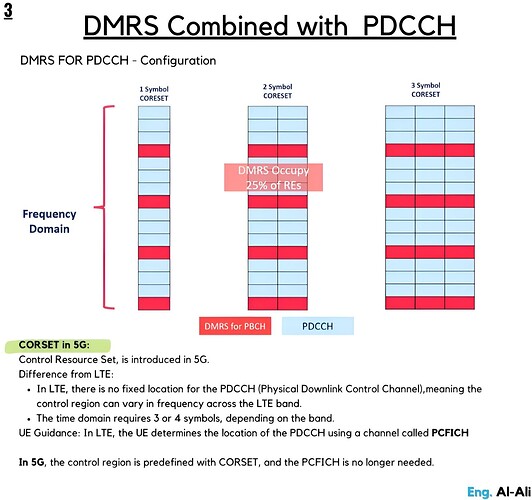
DMRS for PDCCH
DMRS helps the UE estimate the channel for demodulating PDCCH & decoding DCIs
DMRS is transmitted with the PDCCH ![]()
-For each Resource Element Group (REG), there are 3 REs allocated for DMRS.
Each CCE consists of 6 REGs, Since each REG contains 3 REs for DMRS,
the total number of REs allocated for DMRS per CCE is:
6 REGs × 3 REs = 18 REs per CCE.
- PDCCH / DMRS Resource elements are located in a fixed location (1,5, 9, 13,…)
- DMRS for PDCCH Occupy 25% of REs
DMRS for PDSCH
DMRS assists the UE in estimating the radio channel for decoding PDSCH.
- DMRS is always transmitted with PDSCH.
Generally, having more additional DMRS helps the UE decode the PDSCH more reliably, leading to lower BLER, this may reduce the maximum throughput because DMRS takes up resource elements that could otherwise be used for user data, its configuration can vary based on the system’s MIMO mode (SU-MIMO or MU-MIMO).
-
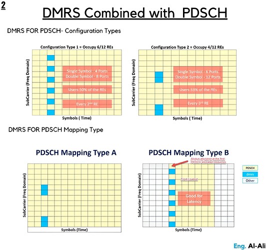
DMRS Configurations: The configuration of DMRS depends on whether SU-MIMO or MU-MIMO is used, which affects the density of REs allocated for DMRS.
-
There are two types of configurations:
Type 1 (Higher Density): Uses 50% of REs within a symbol, suitable for transmissions that require high reliability.
Type 2 (Lower Density): Uses 33% of REs, which allows better frequency multiplexing for MU-MIMO. -
Symbol Configurations: DMRS can use either a single symbol or double symbol configuration. Using two symbols increases the number of antenna ports, which enhances support for MU-MIMO.
-
PDSCH Mapping Types:
Type A: Slot-based scheduling, with DMRS allocated in symbol 2 or 3 of the slot.
Type B: Non-slot-based (mini-slot) scheduling, where DMRS is located in the first symbol, enabling low-latency transmissions.
That’s it.
DMRS
Main Functions of DMRS channel
DMRS Conbined with PBCH
DMRS Conbined with PDSCH
DMRS Conbined with PDCCH
LinkedIn: ![]()
