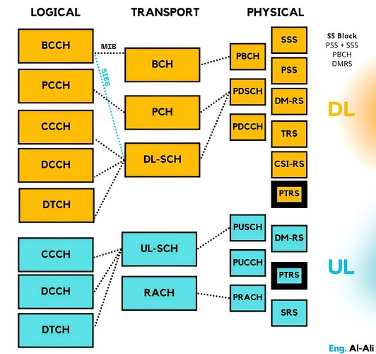
On the air interface between a UE and a 5G base station, 5G New Radio (NR) carries information through different types of channels, which handle both User Plane (UP) and Control Plane (CP) data.
-
Three Types of Channels:
-
Logical Channels: Carry higher-layer information (e.g., data, control).
-
Transport Channels: Interface between MAC and physical layers, providing the mapping to physical channels.
-
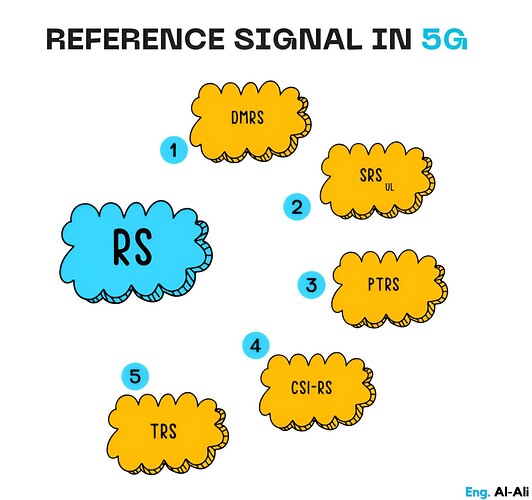
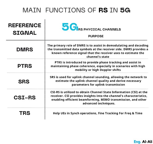
Physical Channels: Carry information over the air interface. Transport channels map to physical channels, while standalone physical channels like PTRS, DMRS, etc., are not directly mapped to higher-layer data but aid in signal transmission and demodulation.
-
-
PTRS:
-
Ever wondered how 5G maintains ultra-fast speeds with stable connections, especially at high frequencies like mmWave?
The Phase Tracking Reference Signal (PTRS) is designed to handle phase noise- short-term signal fluctuations caused by oscillator imperfections.
PTRS helps track and correct these variations, ensuring stable 5G connections, particularly in high-frequency bands.
-
-
What is PTRS?
- PTRS is a newly introduced signal in 5G to mitigate issues related to phase noise and frequency offset, which are more pronounced at high-frequency bands, like mmWave used in 5G.
-
Reasons for Introducing PTRS in 5G:
-
Phase Noise Compensation: At high frequencies (e.g., mmWave), phase noise becomes significant. PTRS helps track and correct short-term phase fluctuations to ensure signal stability.
-
Support for Higher-Order Modulation: Complex modulation schemes like 256-QAM are more sensitive to phase errors. PTRS enables accurate phase tracking, improving demodulation performance.
-
Frequency Offset Mitigation: PTRS compensates for frequency drift, ensuring synchronization between the base station (gNB) and the UE.
-
-
Where is PTRS located?
-
PTRS symbols are inserted into resource blocks within both PDSCH (Physical Downlink Shared Channel) and PUSCH (Physical Uplink Shared Channel).
-
These symbols are sparsely distributed across the time and frequency domains based on channel conditions and modulation schemes.
-
Their primary goal is to assist with phase tracking in scenarios prone to phase noise or frequency drift, such as high-frequency bands (e.g., mmWave) or when using higher-order modulation like 256-QAM.
-
🅣🅗🅐🅣’🅢 🅘🅣 ![]()
LinkedIn: ![]()


