This topic presents in a very simplified way all the main concepts that should be understood by those who know 5G NR.
5G NR Air Interface
The 5G NR air interface introduces significant advancements over LTE, offering greater flexibility, efficiency, and speed. It introduces numerology, which allows multiple subcarrier spacing options (15 to 240 kHz) for better adaptation to different frequencies and use cases. Bandwidth Parts (BWPs) divide the spectrum into smaller segments, optimizing resource use and power efficiency, while Resource Blocks (RBs) and Physical Resource Blocks (PRBs) dynamically adapt to changing conditions. Wider bandwidths (up to 400 MHz in mmWave) and a more flexible frequency raster enable faster speeds and higher capacity. New features like synchronization raster speed up initial connections, and enhanced waveforms like CP-OFDM and DFT-S-OFDM improve consistency and power efficiency. Additionally, the transmitter and receiver chain (Tx/Rx chain), with technologies like massive MIMO and beamforming, supports higher data rates, wider bandwidths, and complex signal processing. Altogether, 5G NR enables faster, more reliable, and efficient wireless communication tailored to diverse applications and devices. [In a Nutshell: 5G NR air interface improves speed, reliability, and flexibility, using advanced technologies like numerology, BWPs, and massive MIMO.]
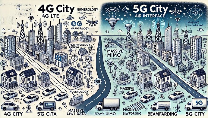
![]() Imagine LTE City as a small, simple town with fixed-width roads and parking spots, where cars (data) follow strict schedules and landmarks (signals) are always in the same place, making it predictable but slow when traffic gets heavy. Now, think of 5G City as a futuristic metropolis with roads that can change size to fit small cars or big trucks, smart parking zones that adapt to save space, and ultra-fast highways and bike lanes for efficient traffic flow. Landmarks are spread across the city for quicker navigation, and flying delivery drones (massive MIMO and beamforming) bypass busy roads to deliver packages directly. This futuristic design allows 5G City to handle way more traffic, move things faster, and ensure everyone gets where they need to go smoothly and efficiently. [In a Nutshell: 5G City’s smart, flexible roads and futuristic upgrades handle more traffic and deliver faster, unlike LTE City’s fixed and slower system.]
Imagine LTE City as a small, simple town with fixed-width roads and parking spots, where cars (data) follow strict schedules and landmarks (signals) are always in the same place, making it predictable but slow when traffic gets heavy. Now, think of 5G City as a futuristic metropolis with roads that can change size to fit small cars or big trucks, smart parking zones that adapt to save space, and ultra-fast highways and bike lanes for efficient traffic flow. Landmarks are spread across the city for quicker navigation, and flying delivery drones (massive MIMO and beamforming) bypass busy roads to deliver packages directly. This futuristic design allows 5G City to handle way more traffic, move things faster, and ensure everyone gets where they need to go smoothly and efficiently. [In a Nutshell: 5G City’s smart, flexible roads and futuristic upgrades handle more traffic and deliver faster, unlike LTE City’s fixed and slower system.]
Skip to: Roadmap to 5G NR
- Numerology
- Radio Frames and Slots
- RB & BWP (Resource Blocks and Bandwidth Parts)
- Common Resource Blocks
- BWP (Bandwidth Parts)
- PRB (Physical Resource Blocks)
- VRB (Virtual Resource Blocks)
- Channel Bandwidths
- Frequency Raster
- Channel Raster
- Synchronisation Raster
- AP & QCL (Antenna Ports and Quasi Co-location)
- Modulation
- CP (Cyclic Prefix)
- Waveform
- CP-OFDM
- DFT-S-OFDM
- Tx/Rx chain (Transmitter and Receiver Chain)
Numerology
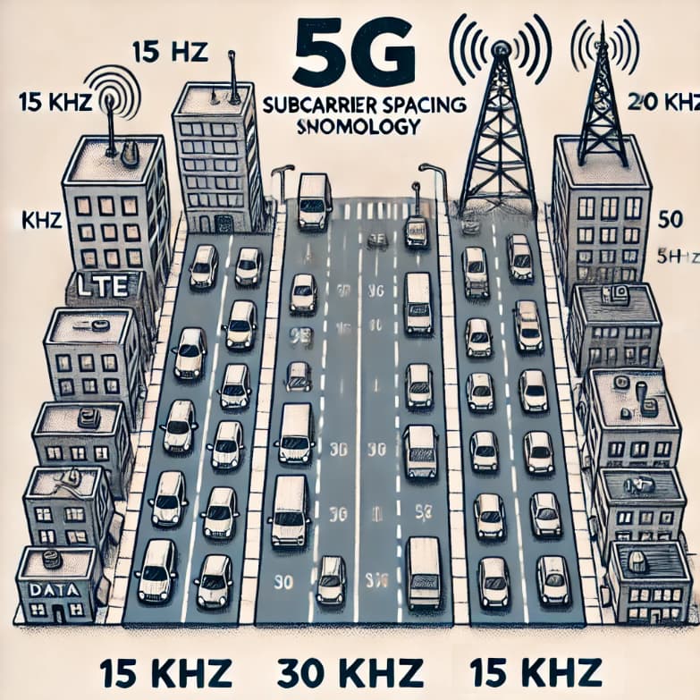
Numerology in 5G NR refers to different subcarrier spacing (SCS) options, which define the distance between adjacent subcarriers in frequency. This is a new concept compared to LTE, where only a fixed 15 kHz SCS is used. In 5G NR, multiple SCS values such as 15, 30, 60, 120, and 240 kHz are supported, enabling flexibility to adapt to various use cases and spectrum bands, such as low latency and high-frequency operations. [In a Nutshell: 5G NR introduces multiple subcarrier spacings to enhance flexibility and support diverse use cases.]
![]() Imagine 5G NR as a city where streets can have different widths for different types of traffic. This “street width” is called numerology, and it decides how far apart cars (data signals) should drive. In LTE City, all streets are the same width, but in 5G City, we have streets of many sizes, like small ones for bikes (low frequencies) and big highways for fast cars (high frequencies). Different roads in our 5G city can change their width to handle more or fewer cars. Numerology is like setting how wide each road (subcarrier spacing) can be, so traffic flows smoothly whether there are lots of cars or just a few. [In a Nutshell: Numerology in 5G is like adjusting street widths to match traffic demands, making data flow smoother.]
Imagine 5G NR as a city where streets can have different widths for different types of traffic. This “street width” is called numerology, and it decides how far apart cars (data signals) should drive. In LTE City, all streets are the same width, but in 5G City, we have streets of many sizes, like small ones for bikes (low frequencies) and big highways for fast cars (high frequencies). Different roads in our 5G city can change their width to handle more or fewer cars. Numerology is like setting how wide each road (subcarrier spacing) can be, so traffic flows smoothly whether there are lots of cars or just a few. [In a Nutshell: Numerology in 5G is like adjusting street widths to match traffic demands, making data flow smoother.]
- Search Forum
 5G NR Numerology
Radio Frames and Slots
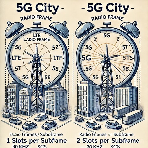
The basic structure of radio frames and slots in 5G NR remains similar to LTE. A radio frame is 10 ms and consists of 10 subframes. However, in 5G NR, the number of slots per subframe depends on numerology. For instance, a 15 kHz SCS results in 1 slot per subframe (like LTE), but a 30 kHz SCS gives 2 slots per subframe. This enhancement allows greater scheduling flexibility. LTE has a similar frame structure, but 5G NR can have more slots per subframe due to varied subcarrier spacings. [In a Nutshell: 5G NR enables flexible slot configurations within frames, enhancing scheduling options.]
![]() In our 5G City, the day is divided into “hours” (radio frames) and “minutes” (slots). In LTE City, every “hour” has the same number of “minutes,” but in 5G City, some “hours” can have more “minutes” if traffic is heavier, making scheduling more flexible. You can also think of it as a big clock ticking every 10 milliseconds (radio frame), divided into 10 smaller ticks (subframes). Each tick is split into slots where cars (data) travel. 5G can have more slots in each tick, or “more minutes in an hour,” than LTE, letting more data move faster. [In a Nutshell: 5G adjusts hours to have more minutes when needed, unlike LTE’s fixed schedule, making data flow faster.]
In our 5G City, the day is divided into “hours” (radio frames) and “minutes” (slots). In LTE City, every “hour” has the same number of “minutes,” but in 5G City, some “hours” can have more “minutes” if traffic is heavier, making scheduling more flexible. You can also think of it as a big clock ticking every 10 milliseconds (radio frame), divided into 10 smaller ticks (subframes). Each tick is split into slots where cars (data) travel. 5G can have more slots in each tick, or “more minutes in an hour,” than LTE, letting more data move faster. [In a Nutshell: 5G adjusts hours to have more minutes when needed, unlike LTE’s fixed schedule, making data flow faster.]
- Search Forum
 5G NR Radio Frames and Slots
RB & BWP (Resource Blocks and Bandwidth Parts)
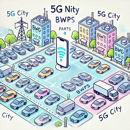
Resource Blocks (RBs) are frequency units used for scheduling, a concept retained from LTE. RBs are the smallest units of resource allocation in both LTE and 5G NR. In 5G NR, Bandwidth Parts (BWPs) are introduced, a new feature that allows flexible and dynamic allocation of RBs across a carrier. UEs can operate within specific BWPs, making spectrum usage more efficient, especially in wideband systems. BWPs allow a carrier to be divided into smaller bandwidths to optimize resource allocation for different use cases. BWPs are a new concept in 5G, enhancing flexibility compared to LTE. [In a Nutshell: 5G NR introduces BWPs for dynamic and efficient spectrum allocation, unlike LTE’s fixed structure.]
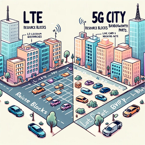
![]() Resource Blocks are like parking spots in the city where vehicles (data) can park. In 5G City, we also have Bandwidth Parts (BWPs), which are like neighborhoods. Each neighborhood can have its own parking rules, making it easier to manage big and small traffic zones. LTE City didn’t have these neighborhoods. In LTE, we had fixed parking spots, but in 5G, BWPs allow us to create flexible parking areas depending on the traffic. [In a Nutshell: BWPs in 5G are like neighborhoods organizing parking for more efficient traffic management.]
Resource Blocks are like parking spots in the city where vehicles (data) can park. In 5G City, we also have Bandwidth Parts (BWPs), which are like neighborhoods. Each neighborhood can have its own parking rules, making it easier to manage big and small traffic zones. LTE City didn’t have these neighborhoods. In LTE, we had fixed parking spots, but in 5G, BWPs allow us to create flexible parking areas depending on the traffic. [In a Nutshell: BWPs in 5G are like neighborhoods organizing parking for more efficient traffic management.]
- Search Forum
 5G NR RB & BWP (Resource Blocks and Bandwidth Parts)
Common Resource Blocks
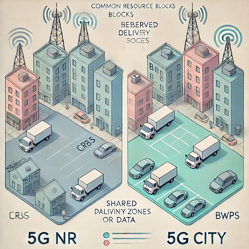
Common Resource Blocks (CRBs) exist in both LTE and 5G NR and provide a universal mapping of RBs across the carrier, independent of BWPs. While the concept is not new, its implementation is critical in multi-BWP scenarios in 5G NR to ensure synchronization and control signal consistency. CRBs in 5G NR are similar to those in LTE, used to allocate resources for downlink and uplink transmissions. There are no significant changes here from LTE. [In a Nutshell: CRBs are shared resources ensuring universal consistency, unchanged from LTE to 5G.]
![]() CRBs are like special reserved parking spots in the city that everyone can use, like loading zones for delivery trucks. These existed in LTE City and continue in 5G City, ensuring smooth operations for everyone, like shared parking spots used by everyone for things like deliveries (control and broadcast data). These exist in both LTE and 5G cities. [In a Nutshell: CRBs are shared delivery zones, ensuring smooth operations in both LTE and 5G cities.]
CRBs are like special reserved parking spots in the city that everyone can use, like loading zones for delivery trucks. These existed in LTE City and continue in 5G City, ensuring smooth operations for everyone, like shared parking spots used by everyone for things like deliveries (control and broadcast data). These exist in both LTE and 5G cities. [In a Nutshell: CRBs are shared delivery zones, ensuring smooth operations in both LTE and 5G cities.]
- Search Forum
 5G NR Common Resource Blocks
BWP (Bandwidth Parts)
BWPs are a new concept in 5G NR. They allow UEs to operate within smaller parts of the overall channel bandwidth, optimizing power consumption and reducing complexity. This capability was not available in LTE, where the UE always operated across the entire carrier bandwidth. As mentioned, BWPs in 5G NR divide a carrier into smaller segments, allowing more efficient use of spectrum based on specific needs. This concept is new to 5G and provides more flexibility than LTE’s fixed bandwidth allocation. [In a Nutshell: BWPs divide 5G’s bandwidth into zones, unlike LTE’s single allocation, making operations more efficient.]
![]() Think of BWPs as different zones in the city, each designed for a specific type of traffic. For example, one zone might allow only small cars, while another handles heavy trucks. This zoning is new in 5G City and helps keep traffic flowing efficiently. Like dividing a big parking lot into smaller, managed sections to better control the flow of cars (data). This makes our 5G city more organized compared to LTE’s single big lot. [In a Nutshell: BWPs are traffic zones in 5G City, improving flow and organization compared to LTE’s single parking lot.]
Think of BWPs as different zones in the city, each designed for a specific type of traffic. For example, one zone might allow only small cars, while another handles heavy trucks. This zoning is new in 5G City and helps keep traffic flowing efficiently. Like dividing a big parking lot into smaller, managed sections to better control the flow of cars (data). This makes our 5G city more organized compared to LTE’s single big lot. [In a Nutshell: BWPs are traffic zones in 5G City, improving flow and organization compared to LTE’s single parking lot.]
- Search Forum
 5G NR BWP (Bandwidth Parts)
PRB (Physical Resource Blocks)
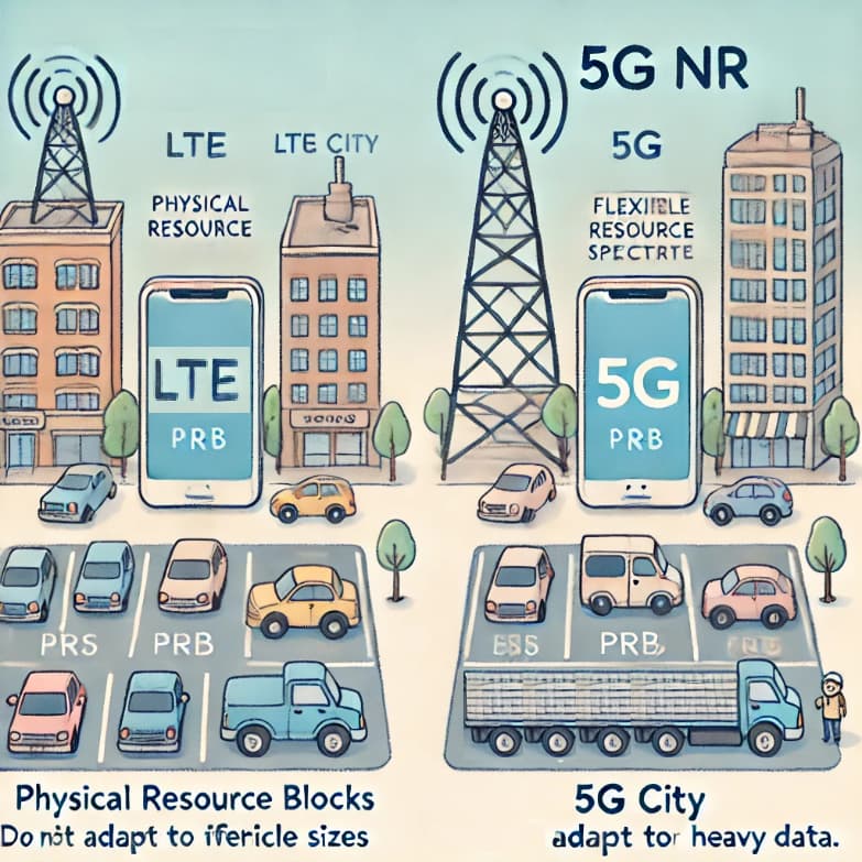
Physical Resource Blocks (PRBs) are frequency-time resource units used for actual transmissions. While PRBs existed in LTE, their bandwidth in 5G NR changes dynamically with numerology, offering better scalability. PRBs are the actual chunks of the spectrum allocated for transmission. Both LTE and 5G NR use PRBs, but 5G NR supports different sizes due to various subcarrier spacings. [In a Nutshell: PRBs in 5G dynamically adjust in size, unlike LTE, offering more scalable spectrum use.]
![]() PRBs are the actual physical parking spots in our city. Just like parking spots in real life, their size can change depending on the neighborhood (BWP). In LTE City, the size was fixed, but in 5G City, it can adjust to fit more vehicles. PRBs are the actual parking spots where data rests. Both LTE and 5G use PRBs, but 5G can adjust the size of these spots to fit more cars if needed. [In a Nutshell: PRBs in 5G City are adjustable parking spots, unlike LTE’s fixed ones, improving flexibility.]
PRBs are the actual physical parking spots in our city. Just like parking spots in real life, their size can change depending on the neighborhood (BWP). In LTE City, the size was fixed, but in 5G City, it can adjust to fit more vehicles. PRBs are the actual parking spots where data rests. Both LTE and 5G use PRBs, but 5G can adjust the size of these spots to fit more cars if needed. [In a Nutshell: PRBs in 5G City are adjustable parking spots, unlike LTE’s fixed ones, improving flexibility.]
- Search Forum
 5G NR PRB (Physical Resource Blocks)
VRB (Virtual Resource Blocks)
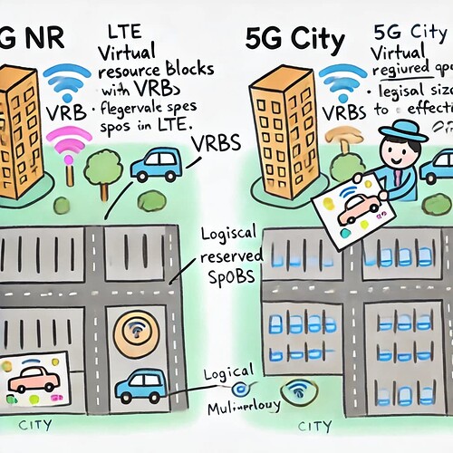
Virtual Resource Blocks (VRBs) are logical units mapped to PRBs for transmission. The concept existed in LTE but is more versatile in 5G NR, as VRB mapping must account for multi-numerology and flexible scheduling. VRBs map logical resource allocations to physical ones. This concept exists in both LTE and 5G NR, with no major changes.[In a Nutshell: VRBs are logical guides for mapping data to physical resources, adaptable in 5G.]
![]() VRBs are like reserved parking spots in the city map. They don’t exist physically but are planned ahead of time to make sure vehicles can park in the right spots. These were in LTE City too, but now they work even better in 5G City. VRBs are like digital maps that show where the parking spots (PRBs) are. Both cities (5G NR and LTE) use these maps to guide data where to park. [In a Nutshell: VRBs are digital parking plans, ensuring data finds the right spot, improved in 5G City.]
VRBs are like reserved parking spots in the city map. They don’t exist physically but are planned ahead of time to make sure vehicles can park in the right spots. These were in LTE City too, but now they work even better in 5G City. VRBs are like digital maps that show where the parking spots (PRBs) are. Both cities (5G NR and LTE) use these maps to guide data where to park. [In a Nutshell: VRBs are digital parking plans, ensuring data finds the right spot, improved in 5G City.]
- Search Forum
 5G NR VRB (Virtual Resource Blocks)
Channel Bandwidths
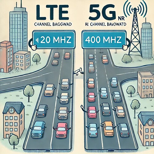
5G NR supports significantly wider channel bandwidths compared to LTE. While LTE’s maximum bandwidth is 20 MHz, 5G NR supports 5 MHz to 100 MHz for sub-6 GHz frequencies and up to 400 MHz in mmWave bands, enabling higher data rates and capacity. LTE supports narrower bandwidths, up to 20 MHz, making 5G more versatile. [In a Nutshell: 5G’s wider bandwidths enable faster speeds and higher capacity compared to LTE.]
![]() Imagine LTE City had small streets, so only a few cars could drive at once. 5G City has super-wide streets (channel bandwidths), letting hundreds of cars zoom by together, especially on the big highways (mmWave bands). Channel Bandwidths in our 5G city are like highways that can be super wide (up to 400 MHz) or smaller (5 MHz). LTE’s highways are narrower, so 5G can handle more traffic and faster speeds. [In a Nutshell: 5G’s highways (channel bandwidths) are much wider, allowing faster and denser traffic than LTE’s narrower streets.]
Imagine LTE City had small streets, so only a few cars could drive at once. 5G City has super-wide streets (channel bandwidths), letting hundreds of cars zoom by together, especially on the big highways (mmWave bands). Channel Bandwidths in our 5G city are like highways that can be super wide (up to 400 MHz) or smaller (5 MHz). LTE’s highways are narrower, so 5G can handle more traffic and faster speeds. [In a Nutshell: 5G’s highways (channel bandwidths) are much wider, allowing faster and denser traffic than LTE’s narrower streets.]
- Search Forum
 5G NR Channel Bandwidths
Frequency Raster
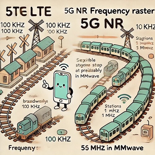
The frequency raster, defining the allowed carrier frequencies, existed in LTE with a fixed spacing of 100 kHz. In 5G NR, it has been expanded for greater flexibility. The spacing remains 100 kHz for sub-6 GHz frequencies, suitable for typical deployments, and increases to 1 MHz for mmWave bands to accommodate wider bandwidths. The Frequency Raster sets the spacing between allowed transmission frequencies, much like marking points on a ruler for precise measurements. In LTE, all key signals, including synchronization and broadcast channels, are fixed in the middle of the frequency band with a single raster spacing of 100 kHz, making it simple and predictable. In 5G, however, these signals are more flexible and can be placed in different positions within the frequency band, thanks to separate rasters for general channel allocation and synchronization signals. This flexibility in 5G allows faster and more efficient network scans and makes better use of wider frequency bands, unlike LTE, which is more rigid in its design. [In a Nutshell: 5G’s flexible frequency raster improves scanning efficiency and bandwidth usage compared to LTE’s fixed design.]
![]() Imagine LTE is like a train schedule where every train (signal) always stops at the same fixed station (frequency) in the middle of the track, making it predictable but inflexible. In contrast, 5G is like a modern transit system where trains can stop at different stations (frequencies) depending on the needs of the passengers (network demands). This flexibility allows 5G to adapt more efficiently, cover more routes (wider bandwidth), and let passengers find their trains (signals) faster, making the system both smarter and quicker than LTE. [In a Nutshell: 5G’s flexible train schedule lets signals stop at various stations, making it faster and more adaptable than LTE’s fixed routes.]
Imagine LTE is like a train schedule where every train (signal) always stops at the same fixed station (frequency) in the middle of the track, making it predictable but inflexible. In contrast, 5G is like a modern transit system where trains can stop at different stations (frequencies) depending on the needs of the passengers (network demands). This flexibility allows 5G to adapt more efficiently, cover more routes (wider bandwidth), and let passengers find their trains (signals) faster, making the system both smarter and quicker than LTE. [In a Nutshell: 5G’s flexible train schedule lets signals stop at various stations, making it faster and more adaptable than LTE’s fixed routes.]
- Search Forum
 5G NR Frequency Raster
Channel Raster
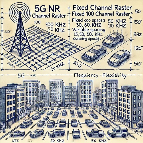
The channel raster in wireless networks defines the specific points (or “slots”) where signals can be transmitted, much like designated parking spots in a parking lot. In LTE (4G), these spots are uniformly spaced at 100 kHz, making it simple and ensuring compatibility across devices. In 5G, the system is more flexible, with multiple spacing options (15, 30, 60, 100, and 120 kHz), allowing better use of the available spectrum and higher efficiency, especially for advanced features like combining multiple “lanes” (carrier aggregation). This flexibility makes 5G more adaptable than LTE while still maintaining compatibility by using the same 100 kHz spacing in lower frequency bands. Channel raster refers to the specific frequencies available for channel placement. 5G NR’s finer frequency raster allows for more precise channel placement compared to LTE. [In a Nutshell: 5G’s flexible channel raster allows for efficient spectrum use and advanced features compared to LTE’s fixed design.]
![]() Imagine LTE is like a city where all the parking spots are the same size, neatly lined up, and you always park in the middle of the lot. It’s easy to find your spot, but it doesn’t make the best use of space. Now, 5G is like an upgraded city where the parking spots are magical - they can change size depending on the size of your car. Small cars get small spots, big trucks get bigger spots, and there are even special areas for combining spots when needed. This enhanced city (5G) uses space much more efficiently than the simple city (LTE) while still keeping some spots the same for old cars to park too. [In a Nutshell: 5G’s magical parking spots adjust for efficient space use, unlike LTE’s fixed ones.]
Imagine LTE is like a city where all the parking spots are the same size, neatly lined up, and you always park in the middle of the lot. It’s easy to find your spot, but it doesn’t make the best use of space. Now, 5G is like an upgraded city where the parking spots are magical - they can change size depending on the size of your car. Small cars get small spots, big trucks get bigger spots, and there are even special areas for combining spots when needed. This enhanced city (5G) uses space much more efficiently than the simple city (LTE) while still keeping some spots the same for old cars to park too. [In a Nutshell: 5G’s magical parking spots adjust for efficient space use, unlike LTE’s fixed ones.]
- Search Forum
 5G NR Channel Raster
Synchronisation Raster
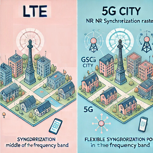
Synchronization raster is a new concept in 5G NR, defining specific locations for transmitting synchronization signals, including how often these signals are transmitted. It specifies the points where key signals, such as the Synchronization Signal and Broadcast Channel (SS/PBCH), can be placed within the network. Unlike LTE, where these signals are always fixed in the center of the frequency band, 5G introduces flexible placement, using a system of designated spots called Global Synchronisation Channel Numbers (GSCNs). This flexibility enables devices (UEs) to quickly find and connect to the network during their initial search, making the process faster and more efficient than in LTE. It is particularly beneficial in scenarios involving multiple numerologies and wider bandwidths. [In a Nutshell: 5G’s synchronization raster improves connection speed and flexibility compared to LTE’s fixed approach.]
![]() Imagine LTE is like a city where all the landmarks, like parks or statues, are always in the exact center of their neighborhoods, making it simple but sometimes slow to navigate since you always have to go to the center. 5G, on the other hand, is like an upgraded city where landmarks are spread across neighborhoods at smart locations, making it quicker and easier to find them. This smarter design helps everything in 5G work faster and more efficiently compared to LTE. It’s like upgrading from a fixed meeting point in a city to a system of multiple well-marked landmarks that make navigation much easier. [In a Nutshell: 5G spreads landmarks intelligently, speeding up connections compared to LTE’s fixed central points.]
Imagine LTE is like a city where all the landmarks, like parks or statues, are always in the exact center of their neighborhoods, making it simple but sometimes slow to navigate since you always have to go to the center. 5G, on the other hand, is like an upgraded city where landmarks are spread across neighborhoods at smart locations, making it quicker and easier to find them. This smarter design helps everything in 5G work faster and more efficiently compared to LTE. It’s like upgrading from a fixed meeting point in a city to a system of multiple well-marked landmarks that make navigation much easier. [In a Nutshell: 5G spreads landmarks intelligently, speeding up connections compared to LTE’s fixed central points.]
- Search Forum
 5G NR Synchronisation Raster
AP & QCL (Antenna Ports and Quasi Co-location)
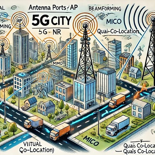
Antenna Ports (AP) and Quasi Co-location (QCL) existed in LTE but are enhanced in 5G NR. Antenna ports are like virtual pathways (logical antennas) that signals travel through, and they don’t always correspond directly to physical antennas. These ports help ensure that signals either share the same channel for smooth decoding, like when your phone picks up the signal for a specific service, or have separate channels to send multiple data streams simultaneously, like different voices in a choir. Devices, like smartphones, don’t need to know which physical antenna is being used—they just focus on understanding the signal patterns. This system allows advanced techniques like beamforming (targeted signals) and MIMO (multiple data streams) to work seamlessly, improving speed and reliability in 5G networks. Quasi Co-location (QCL) allows UEs to assume shared properties (like timing or beam direction) between signals transmitted from different APs, improving efficiency in beamforming scenarios. Quasi Co-location (QCL) indicates that different signals experience similar channel conditions. This concept exists in LTE but is more advanced in 5G NR due to the use of Massive MIMO. It’s crucial to distinguish between logical ‘antenna ports’ and physical ‘antenna elements.’ Each transmission uses a specific antenna port, which is then mapped to one or more physical antenna elements. [In a Nutshell: Antenna Ports are virtual pathways for signals, enabling techniques like beamforming and MIMO, while QCL ensures shared properties across signals for efficiency in scenarios like Massive MIMO.]
![]() Antenna Ports are like broadcasting towers in the city, sending traffic updates to drivers. QCL ensures these towers coordinate their messages (different towers that are close to each other and experience the same conditions) so drivers don’t get confused, especially when switching streets. In LTE City, there are pathways (antenna ports) that carry signals, like mail trucks delivering letters. Each truck knows its route, but there aren’t too many trucks, so the city runs okay but not super fast. In 5G City, the pathways (antenna ports) are upgraded, and now there are way more trucks, and some can even carry multiple packages at once (MIMO). Plus, there are smart traffic rules (Quasi Co-location) that let trucks from different routes share shortcuts if they’re going in the same direction, making deliveries faster and more efficient. This upgrade helps everyone in 5G City get their packages quicker, no matter how many there are! [In a Nutshell: 5G’s upgraded trucks (APs) and smart traffic rules (QCL) deliver faster and more efficiently than LTE.]
Antenna Ports are like broadcasting towers in the city, sending traffic updates to drivers. QCL ensures these towers coordinate their messages (different towers that are close to each other and experience the same conditions) so drivers don’t get confused, especially when switching streets. In LTE City, there are pathways (antenna ports) that carry signals, like mail trucks delivering letters. Each truck knows its route, but there aren’t too many trucks, so the city runs okay but not super fast. In 5G City, the pathways (antenna ports) are upgraded, and now there are way more trucks, and some can even carry multiple packages at once (MIMO). Plus, there are smart traffic rules (Quasi Co-location) that let trucks from different routes share shortcuts if they’re going in the same direction, making deliveries faster and more efficient. This upgrade helps everyone in 5G City get their packages quicker, no matter how many there are! [In a Nutshell: 5G’s upgraded trucks (APs) and smart traffic rules (QCL) deliver faster and more efficiently than LTE.]
- Search Forum
 5G NR AP & QCL (Antenna Ports and Quasi Co-location)
Modulation
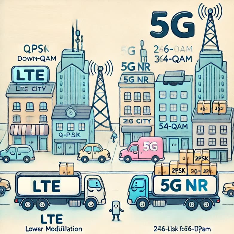
Both LTE and 5G NR support Quadrature Amplitude Modulation (QAM). However, 5G NR enhances this by supporting 256-QAM for both downlink and uplink, improving spectral efficiency compared to LTE, which maxes at 64-QAM in uplink. Modulation schemes in 5G NR include QPSK, 16QAM, 64QAM, and 256QAM, similar to LTE. However, 5G NR can achieve higher data rates due to its enhanced flexibility and efficiency. [In a Nutshell: 5G supports higher modulation (256-QAM), improving efficiency and data rates over LTE.]
![]() Modulation is like the type of cargo each car carries. In LTE City, some cars carried basic goods, but in 5G City, vehicles can carry premium, heavy-duty goods (like 256-QAM), delivering more value in a single trip. Modulation is like how we load and send out trucks (data). Both LTE and 5G use different ways to pack the trucks (QPSK, 16QAM, 64QAM, 256QAM), but 5G does it more efficiently and faster. [In a Nutshell: 5G packs cars with heavier and more valuable goods (256-QAM), making delivery faster and more efficient than LTE.]
Modulation is like the type of cargo each car carries. In LTE City, some cars carried basic goods, but in 5G City, vehicles can carry premium, heavy-duty goods (like 256-QAM), delivering more value in a single trip. Modulation is like how we load and send out trucks (data). Both LTE and 5G use different ways to pack the trucks (QPSK, 16QAM, 64QAM, 256QAM), but 5G does it more efficiently and faster. [In a Nutshell: 5G packs cars with heavier and more valuable goods (256-QAM), making delivery faster and more efficient than LTE.]
- Search Forum
 5G NR Modulation
CP (Cyclic Prefix)
CP (Cyclic Prefix)
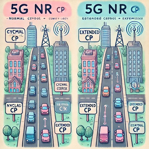
The Cyclic Prefix (CP) prevents interference between OFDM symbols. It exists in both LTE and 5G NR, but 5G NR offers more options. In addition to the normal CP, an extended CP is available for specific high-mobility environments. CP is used to combat inter-symbol interference. Both LTE and 5G NR use CP, but 5G NR offers more options for CP lengths, improving performance under various conditions. [In a Nutshell: 5G adds extended CP options to handle interference better in diverse environments compared to LTE.]
![]() The cyclic prefix is like a safety buffer on roads to avoid car crashes (signal interference). LTE City had this, but 5G City added more options for different kinds of roads, making traffic smoother even at high speeds. [In a Nutshell: 5G’s expanded safety buffers keep traffic (signals) flowing smoothly, even on faster roads.]
The cyclic prefix is like a safety buffer on roads to avoid car crashes (signal interference). LTE City had this, but 5G City added more options for different kinds of roads, making traffic smoother even at high speeds. [In a Nutshell: 5G’s expanded safety buffers keep traffic (signals) flowing smoothly, even on faster roads.]
- Search Forum
 5G NR CP (Cyclic Prefix)
Waveform
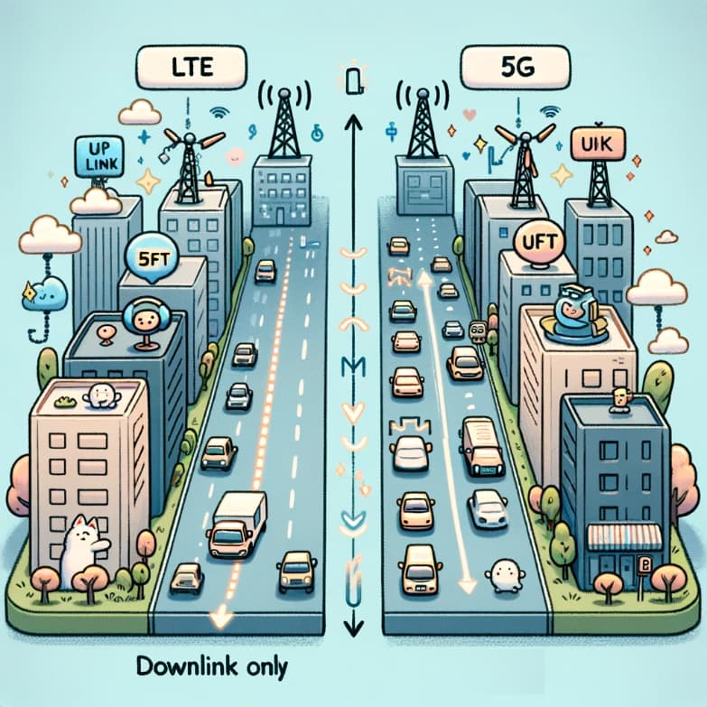
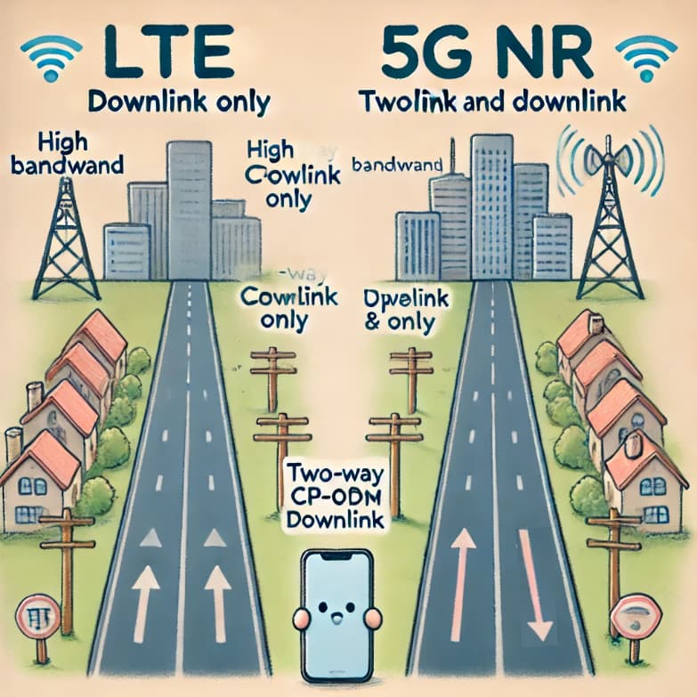
The waveform in 5G NR is based on OFDM, like LTE. 5G NR primarily uses CP-OFDM for both uplink and downlink, unlike LTE, where CP-OFDM was used only in the downlink. This change ensures greater consistency and efficiency. Additionally, 5G NR supports DFT-S-OFDM as an alternative waveform for uplink transmissions, offering lower PAPR for power-sensitive devices. [In a Nutshell: 5G improves consistency by using CP-OFDM for both directions and introduces DFT-S-OFDM for power-efficient uplink.]
![]() The waveform is like the kind of road built in a city. In LTE City, there was mainly one type of road used for traffic in one direction (downlink). In 5G City, the same type of road is now used for both directions, making traffic flow smoother. 5G also builds new types of roads (waveforms) for special purposes, making the city more versatile and efficient. [In a Nutshell: 5G’s roads (waveforms) support two-way traffic and special needs, improving flow and versatility over LTE.]
The waveform is like the kind of road built in a city. In LTE City, there was mainly one type of road used for traffic in one direction (downlink). In 5G City, the same type of road is now used for both directions, making traffic flow smoother. 5G also builds new types of roads (waveforms) for special purposes, making the city more versatile and efficient. [In a Nutshell: 5G’s roads (waveforms) support two-way traffic and special needs, improving flow and versatility over LTE.]
- Search Forum
 5G NR Waveform
CP-OFDM
Cyclic Prefix Orthogonal Frequency Division Multiplexing (CP-OFDM) forms the core of 5G NR waveforms. Its flexibility with multi-numerology and support for massive bandwidths make it a key advancement over LTE’s fixed OFDM implementation. It is the primary downlink waveform in 5G NR, providing robustness against multipath interference. This is also used in LTE. [In a Nutshell: CP-OFDM is the core waveform in 5G, flexible and robust, supporting wide bandwidths better than LTE.]
![]() CP-OFDM is the main road-building style in 5G City. It’s smooth, efficient, and works well for the new wide roads (high bandwidth). LTE City also used this, but only in one direction, while 5G City uses it everywhere. [In a Nutshell: CP-OFDM is the standard, reliable pavement for 5G’s two-way traffic, improving on LTE’s one-way use.]
CP-OFDM is the main road-building style in 5G City. It’s smooth, efficient, and works well for the new wide roads (high bandwidth). LTE City also used this, but only in one direction, while 5G City uses it everywhere. [In a Nutshell: CP-OFDM is the standard, reliable pavement for 5G’s two-way traffic, improving on LTE’s one-way use.]
- Search Forum
 5G NR CP-OFDM
DFT-S-OFDM
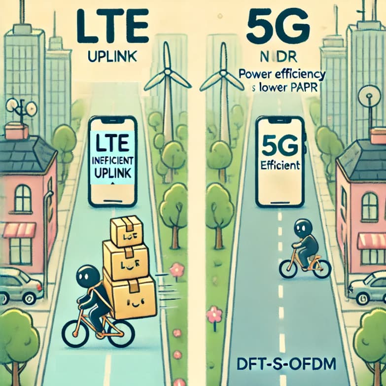
Discrete Fourier Transform Spread OFDM (DFT-S-OFDM) is retained in 5G NR for uplink transmissions, providing efficient power usage. It is similar to the SC-FDMA used in LTE. Its lower peak-to-average power ratio (PAPR) improves efficiency, particularly for battery-powered devices, similar to its role in LTE. DFT-S-OFDM is like a special tool used in 5G’s uplink to make signals travel farther and work better in areas with poor coverage, like sending a clear message through a noisy room. It uses a clever process called Transform Precoding to organize and smooth the signal, making it less spiky (lowering PAPR). This helps devices like smartphones use their power more efficiently, sending stronger signals without needing more energy. Although it doesn’t work for super-fast or multi-layer data streams like MIMO, it’s perfect for boosting signal strength when coverage is a challenge. [In a Nutshell: DFT-S-OFDM improves uplink efficiency in 5G, ideal for coverage-limited areas and power-saving needs.]
![]() In LTE City, when people send letters (signals), they stuff them into bulky packages (high peaks) and send them as is, which can be hard for smaller messengers (phones) to carry, especially over long distances. In 5G City, there’s a magical envelope system (DFT-S-OFDM) that flattens these packages, making them easier to carry and ensuring the letters arrive neatly and readable. It’s like adding a special bike lane in the city—designed for smaller vehicles to travel energy-efficiently. LTE City had this lane for bike traffic, but 5G City improved it for smoother rides, making it ideal for power-saving and coverage-limited roads. [In a Nutshell: DFT-S-OFDM in 5G is like a bike lane, improving energy-efficient, long-distance communication compared to LTE.]
In LTE City, when people send letters (signals), they stuff them into bulky packages (high peaks) and send them as is, which can be hard for smaller messengers (phones) to carry, especially over long distances. In 5G City, there’s a magical envelope system (DFT-S-OFDM) that flattens these packages, making them easier to carry and ensuring the letters arrive neatly and readable. It’s like adding a special bike lane in the city—designed for smaller vehicles to travel energy-efficiently. LTE City had this lane for bike traffic, but 5G City improved it for smoother rides, making it ideal for power-saving and coverage-limited roads. [In a Nutshell: DFT-S-OFDM in 5G is like a bike lane, improving energy-efficient, long-distance communication compared to LTE.]
- Search Forum
 5G NR DFT-S-OFDM
Tx/Rx chain (Transmitter and Receiver Chain)
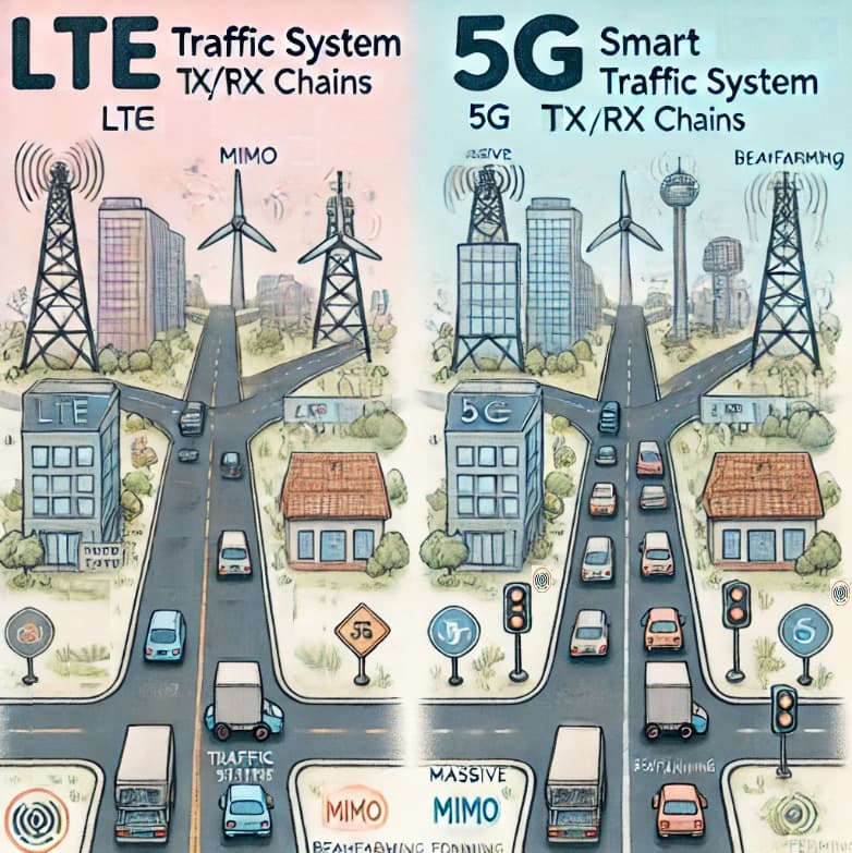
The transmitter and receiver in 5G form a two-way communication system, where one side sends messages and the other side decodes them. The transmitter boosts signal strength using a power amplifier, while the receiver enhances incoming signals with a low-noise amplifier for clear decoding. To prevent signal overlap and delays, a “buffer zone” called a cyclic prefix is added during transmission and removed during reception. In 5G, the transmitter and receiver chain (Tx/Rx chain) is enhanced with advanced features like massive MIMO and beamforming, enabling higher data rates, wider bandwidths, and more complex antenna configurations. These innovations make 5G NR significantly more capable and efficient than LTE. The transmitter and receiver chain in 5G NR is designed to handle higher data rates and more complex signal processing. [In a Nutshell: 5G’s Tx/Rx chain upgrades enable higher data rates and efficient signal processing compared to LTE.]
![]() The Tx/Rx chain is like the city’s entire traffic system, including road signs, traffic signals, and toll booths. In 5G City, this system has been upgraded with advanced technology, like automated intersections (massive MIMO and beamforming), to handle more vehicles and faster traffic without slowing down. This enhanced Transmitter and Receiver Chain ensures smooth traffic flow, even during rush hours, making it much more efficient than LTE City’s older system. [In a Nutshell: 5G City’s upgraded traffic system (Tx/Rx chain) handles more vehicles faster and more efficiently than LTE City.]
The Tx/Rx chain is like the city’s entire traffic system, including road signs, traffic signals, and toll booths. In 5G City, this system has been upgraded with advanced technology, like automated intersections (massive MIMO and beamforming), to handle more vehicles and faster traffic without slowing down. This enhanced Transmitter and Receiver Chain ensures smooth traffic flow, even during rush hours, making it much more efficient than LTE City’s older system. [In a Nutshell: 5G City’s upgraded traffic system (Tx/Rx chain) handles more vehicles faster and more efficiently than LTE City.]
- Search Forum
 5G NR Tx/Rx chain (Transmitter and Receiver Chain)
That’s it. ![]()
-
Continue reading: Roadmap to 5G NR - Downlink Signals and Channels
-
Or back to: Roadmap to 5G NR
