This topic presents in a very simplified way all the main concepts that should be understood by those who know 5G NR.
5G NR Radio Network Planning
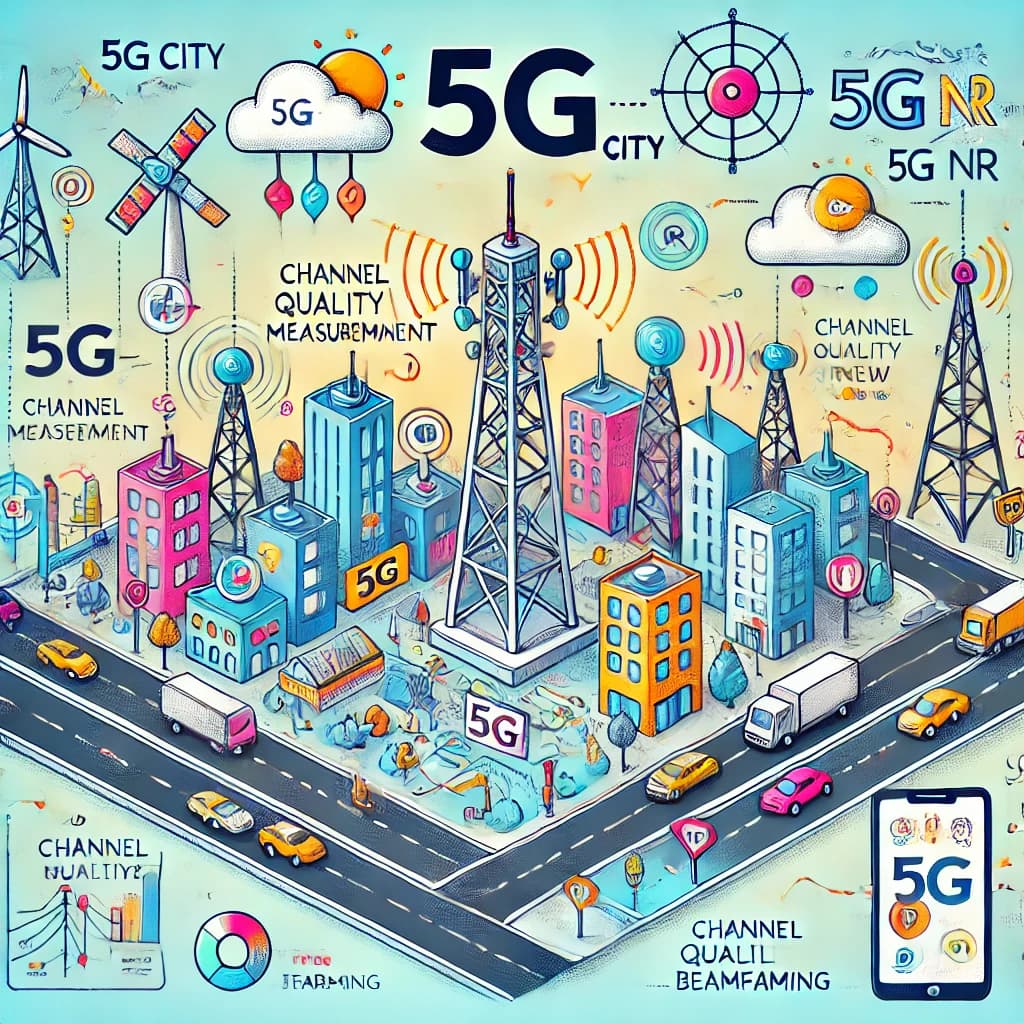
5G NR Radio Network Planning involves organizing various technical aspects to ensure efficient and reliable communication. Operating Bands define the frequency ranges used, with identifiers like NR-ARFCN and GSCN specifying center frequencies for channels and synchronization signals. Slot Formats determine how time slots are divided for uplink, downlink, and guard periods, directly influencing latency, throughput, and cell range. Advanced Antenna Solutions enable beamforming for precise coverage, and Downlink Transmit Power is carefully managed to optimize signal reach while minimizing interference. PCI Allocation ensures unique identifiers for cells to avoid collisions, and Cyclic Prefix protects transmissions from delay spread in challenging environments. CSI Reference Signal and Phase Tracking Reference Signal enhance channel quality and signal reliability. PRACH Planning, including PRACH Format, Configuration Index, Zero Correlation Zone, High-Speed Flag, Root Sequence Index, and Frequency Offset, facilitates initial access and synchronization tailored to diverse deployments. Neighbour Planning and Cell & BTS Identity Planning ensure seamless handovers and efficient mobility management. RAN Notification Area Planning and Tracking Area Planning reduce signaling load during idle states and improve paging efficiency. Finally, Throughput Expectations, including Downlink and Uplink Throughput, help optimize data rates by considering network capacity, overhead, and advanced features like MIMO and high-order modulation. Compared to LTE, 5G NR introduces enhanced flexibility, scalability, and efficiency for diverse deployment scenarios. [In a Nutshell: 5G NR ensures efficient communication with advanced planning, reliable connections, and improved flexibility compared to LTE.]
![]() Imagine LTE City and 5G City as two towns. LTE City is like a smaller, simpler place where things work well but are a bit limited. 5G City, though, is a super-modern town built to handle all kinds of activities. The Operating Band is like the area where the city is built, and addresses like NR-ARFCN and GSCN help everyone find their way to the right place. The town’s schedule (Slot Format) organizes when deliveries (uplink and downlink) happen and when roads are closed for repairs (guard periods). Towers with advanced equipment (Antenna Solutions) send messages to homes more precisely, and the town’s power system (Downlink Transmit Power) ensures messages reach faraway places without causing too much noise. In 5G City, every house has a unique number (PCI Allocation) to avoid mix-ups, and roads have special lanes (Cyclic Prefix) to keep traffic moving even during jams. Helpers like CSI Reference Signal and Phase Tracking Reference Signal make sure messages stay clear and steady. The gates into the city (PRACH Planning) are better organized with different types of entrances (PRACH Format), schedules (Configuration Index), and rules like Zero Correlation Zone and High-Speed Flag to handle both slow walkers and fast runners. Signs (Root Sequence Index) guide people to the right gates, and the city’s planners avoid blocking main roads (PRACH Frequency Offset) to keep things smooth. When people move around (Neighbour Planning), the city ensures all areas are connected so no one gets lost. Every neighborhood (Cell & BTS Identity Planning) has a clear address, and quiet zones (RAN Notification Area Planning) let people rest without constantly checking in. The town also splits into regions (Tracking Area Planning) to handle busy areas without too much work. Finally, the delivery system (Throughput Expectations) is super fast, handling both sending (Uplink Throughput) and receiving (Downlink Throughput) packages efficiently, making 5G City the most advanced and organized place to live. [In a Nutshell: 5G City is a modern, efficient town where everything is planned to handle activities better than LTE City.]
Imagine LTE City and 5G City as two towns. LTE City is like a smaller, simpler place where things work well but are a bit limited. 5G City, though, is a super-modern town built to handle all kinds of activities. The Operating Band is like the area where the city is built, and addresses like NR-ARFCN and GSCN help everyone find their way to the right place. The town’s schedule (Slot Format) organizes when deliveries (uplink and downlink) happen and when roads are closed for repairs (guard periods). Towers with advanced equipment (Antenna Solutions) send messages to homes more precisely, and the town’s power system (Downlink Transmit Power) ensures messages reach faraway places without causing too much noise. In 5G City, every house has a unique number (PCI Allocation) to avoid mix-ups, and roads have special lanes (Cyclic Prefix) to keep traffic moving even during jams. Helpers like CSI Reference Signal and Phase Tracking Reference Signal make sure messages stay clear and steady. The gates into the city (PRACH Planning) are better organized with different types of entrances (PRACH Format), schedules (Configuration Index), and rules like Zero Correlation Zone and High-Speed Flag to handle both slow walkers and fast runners. Signs (Root Sequence Index) guide people to the right gates, and the city’s planners avoid blocking main roads (PRACH Frequency Offset) to keep things smooth. When people move around (Neighbour Planning), the city ensures all areas are connected so no one gets lost. Every neighborhood (Cell & BTS Identity Planning) has a clear address, and quiet zones (RAN Notification Area Planning) let people rest without constantly checking in. The town also splits into regions (Tracking Area Planning) to handle busy areas without too much work. Finally, the delivery system (Throughput Expectations) is super fast, handling both sending (Uplink Throughput) and receiving (Downlink Throughput) packages efficiently, making 5G City the most advanced and organized place to live. [In a Nutshell: 5G City is a modern, efficient town where everything is planned to handle activities better than LTE City.]
Skip to: Roadmap to 5G NR
- Operating Band
- NR-ARFCN & GSCN
- Slot Format
- Antenna Solution
- Downlink Transmit Power
- PCI Allocation
- Cyclic Prefix
- CSI Reference Signal
- Phase Tracking Reference Signal
- PRACH Planning
- PRACH Format
- PRACH Configuration Index
- Zero Correlation Zone
- High-Speed Flag
- Root Sequence Index
- PRACH Frequency Offset
- Neighbour Planning
- Cell & BTS Identity Planning
- RAN Notification Area Planning
- Tracking Area Planning
- Throughput Expectations
- Downlink Throughput
- Uplink Throughput
Operating Band
In 5G NR, the Operating Band refers to the specific frequency ranges used for network operations, categorized into Frequency Range 1 (sub-6 GHz) and Frequency Range 2 (mmWave). While many spectrum allocations correspond to a single operating band, overlapping bands (e.g., n77 and n78) can be associated with the same spectrum, requiring careful selection based on deployment needs. This selection may depend on compatibility with band combinations necessary for LTE-NR Non-Standalone (NSA) architecture, NR Carrier Aggregation, or Dual Connectivity. Unlike LTE, where operating bands were simpler, NR allows multiple bands to be configured and broadcast via SIB1, offering more flexibility but requiring thorough checks to ensure that both network equipment and user devices support the required combinations. This ensures optimal performance and compatibility across deployments. [In a Nutshell: 5G NR Operating Bands offer flexibility and support advanced deployment needs compared to LTE.]
![]() Imagine LTE and 5G are two big cities with roads for cars (frequency ranges). In LTE City, the roads are simple and usually go to just one destination. But in 5G City, there are two types of roads: wide highways (Frequency Range 1) and super-speed skyways (Frequency Range 2). Some highways and skyways overlap, so city planners have to decide carefully which road to use for certain vehicles (devices) to avoid confusion. 5G City also allows more roads to be connected and shared, making travel faster and more flexible, but it requires extra checks to ensure every vehicle can use the roads properly. This makes 5G City more advanced and efficient than LTE City! [In a Nutshell: 5G City has modern roads, making travel faster and flexible, but with extra planning to keep it smooth.]
Imagine LTE and 5G are two big cities with roads for cars (frequency ranges). In LTE City, the roads are simple and usually go to just one destination. But in 5G City, there are two types of roads: wide highways (Frequency Range 1) and super-speed skyways (Frequency Range 2). Some highways and skyways overlap, so city planners have to decide carefully which road to use for certain vehicles (devices) to avoid confusion. 5G City also allows more roads to be connected and shared, making travel faster and more flexible, but it requires extra checks to ensure every vehicle can use the roads properly. This makes 5G City more advanced and efficient than LTE City! [In a Nutshell: 5G City has modern roads, making travel faster and flexible, but with extra planning to keep it smooth.]
- Search Forum
 5G NR Operating Band
NR-ARFCN & GSCN
In 5G NR, NR-ARFCN (New Radio Absolute Radio Frequency Channel Number) and GSCN (Global Synchronization Channel Number) play a critical role in identifying center frequencies for both channel bandwidth and synchronization signals. NR-ARFCN determines the center frequency of the channel, requiring alignment with operating band rasters and calculated using a standard formula. This approach is similar to LTE’s ARFCN but introduces additional flexibility with multiple channel rasters in some bands. GSCN, unique to NR, identifies frequencies for SS/PBCH Blocks, ensuring proper subcarrier alignment and placement within the channel. Unlike LTE, NR allows advanced configurations like multiple SS/PBCH Blocks and flexible placement within the channel bandwidth, optimizing synchronization and measurement accuracy while balancing resource allocation for other signals. [In a Nutshell: NR-ARFCN and GSCN enable flexible frequency and synchronization configurations, advancing beyond LTE.]
![]() Imagine LTE City and 5G City as two neighborhoods with musical orchestras. In LTE City, each orchestra uses a simple tuning system (ARFCN) to decide what note (frequency) to play so they can stay in harmony. In 5G City, the orchestras use a new system called NR-ARFCN, which can handle more complicated tunes (multiple rasters) for bigger and better performances. On top of that, 5G City introduces GSCN, like a special tuning fork that helps each section of the orchestra stay perfectly aligned, even when playing in different parts of the city. This makes the music in 5G City richer, more flexible, and perfectly in sync! [In a Nutshell: 5G City orchestras use smarter tools to make music richer and more synchronized than LTE City.]
Imagine LTE City and 5G City as two neighborhoods with musical orchestras. In LTE City, each orchestra uses a simple tuning system (ARFCN) to decide what note (frequency) to play so they can stay in harmony. In 5G City, the orchestras use a new system called NR-ARFCN, which can handle more complicated tunes (multiple rasters) for bigger and better performances. On top of that, 5G City introduces GSCN, like a special tuning fork that helps each section of the orchestra stay perfectly aligned, even when playing in different parts of the city. This makes the music in 5G City richer, more flexible, and perfectly in sync! [In a Nutshell: 5G City orchestras use smarter tools to make music richer and more synchronized than LTE City.]
- Search Forum 5G NR NR-ARFCN & GSCN
Slot Format
In 5G NR, Slot Format determines how time slots are divided into uplink, downlink, and guard periods, particularly for TDD operations. While LTE used static configurations, NR introduces semi-static and dynamic slot formats, with initial deployments favoring semi-static formats due to cross-link interference challenges. Slot Formats directly impact key network aspects, such as the number of SS/PBCH beams, PRACH configurations, cell range, and the uplink/downlink throughput balance. They influence guard period durations, which accommodate propagation delays and transceiver switching, ultimately defining the maximum cell range. Additionally, slot formats with more distributed uplink slots improve latency but increase guard period overhead, reducing overall throughput efficiency. Selecting the optimal Slot Format requires balancing latency, cell range, and throughput requirements, adapting to deployment scenarios. [In a Nutshell: Slot Format organizes time slots in NR to balance latency, range, and throughput while adapting to different deployment needs.]
![]() Imagine LTE City and 5G City as two towns with a bus schedule. In LTE City, buses follow a fixed schedule (static configurations), with separate times for picking up passengers (uplink) and dropping them off (downlink). In 5G City, the bus schedule is more flexible, with semi-static and dynamic options, allowing adjustments based on traffic and passenger needs. Some routes have shorter breaks (guard periods) between trips to reach distant neighborhoods (cell range), while others balance trips evenly to reduce waiting times (latency). The planners in 5G City carefully design these schedules to ensure everyone gets where they need to go efficiently, adapting routes to suit different areas and avoid traffic jams. [In a Nutshell: Slot Format in 5G City makes bus schedules flexible, improving efficiency and adapting to traffic and distance challenges.]
Imagine LTE City and 5G City as two towns with a bus schedule. In LTE City, buses follow a fixed schedule (static configurations), with separate times for picking up passengers (uplink) and dropping them off (downlink). In 5G City, the bus schedule is more flexible, with semi-static and dynamic options, allowing adjustments based on traffic and passenger needs. Some routes have shorter breaks (guard periods) between trips to reach distant neighborhoods (cell range), while others balance trips evenly to reduce waiting times (latency). The planners in 5G City carefully design these schedules to ensure everyone gets where they need to go efficiently, adapting routes to suit different areas and avoid traffic jams. [In a Nutshell: Slot Format in 5G City makes bus schedules flexible, improving efficiency and adapting to traffic and distance challenges.]
- Search Forum 5G NR Slot Format
Antenna Solution
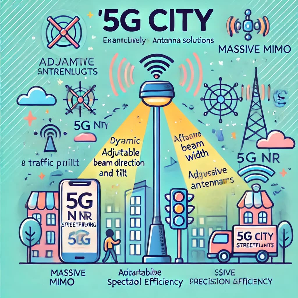
5G NR supports advanced antenna solutions, including Massive MIMO and active antenna systems, to enable beamforming and spatial multiplexing. In 5G NR, Antenna Solutions vary significantly between Frequency Range 1 (sub-6 GHz) and Frequency Range 2 (mmWave). For Frequency Range 2, active antenna arrays are typically required to meet link budget demands, with beamforming primarily enhancing coverage. For Frequency Range 1, passive antennas, often paired with Remote Radio Heads (RRH), and active antennas are both viable. Active antennas enable advanced beamforming in azimuth and elevation directions, offering configurations like 16Tx16Rx, 32Tx32Rx, or 64Tx64Rx for higher precision and spectral efficiency. Passive antennas, while cost-effective, provide less refined beamforming. Key considerations for antenna selection include technical specifications, cost, and deployment practicality. Active antennas offer additional flexibility with adjustable beamwidths and downtilts, optimizing coverage and minimizing interference. Compared to LTE, NR’s advanced antenna solutions allow for greater network flexibility, precision, and scalability, especially in dense and high-frequency deployments. [In a Nutshell: 5G NR antenna solutions, including active and passive options, enhance beamforming and scalability, adapting to diverse deployment needs across frequencies.]
![]() Imagine LTE City and 5G City as towns with streetlights guiding traffic. In LTE City, the streetlights are simple, fixed lamps (passive antennas) that light up large areas but can’t direct light precisely. In 5G City, the streetlights are advanced and come in two types: standard lamps for regular streets (Frequency Range 1) and powerful, adjustable lamps for busy highways (Frequency Range 2). The adjustable lamps (active antennas) can focus their beams on specific spots, helping guide traffic efficiently, even on crowded roads. These advanced lights can also tilt and change their width to adapt to different traffic patterns, making 5G City much better equipped to handle complex and high-speed traffic compared to LTE City. [In a Nutshell: 5G City uses advanced adjustable streetlights (active antennas) for precise traffic control, unlike LTE City’s simpler fixed lights.]
Imagine LTE City and 5G City as towns with streetlights guiding traffic. In LTE City, the streetlights are simple, fixed lamps (passive antennas) that light up large areas but can’t direct light precisely. In 5G City, the streetlights are advanced and come in two types: standard lamps for regular streets (Frequency Range 1) and powerful, adjustable lamps for busy highways (Frequency Range 2). The adjustable lamps (active antennas) can focus their beams on specific spots, helping guide traffic efficiently, even on crowded roads. These advanced lights can also tilt and change their width to adapt to different traffic patterns, making 5G City much better equipped to handle complex and high-speed traffic compared to LTE City. [In a Nutshell: 5G City uses advanced adjustable streetlights (active antennas) for precise traffic control, unlike LTE City’s simpler fixed lights.]
- Search Forum 5G NR Antenna Solution
Downlink Transmit Power
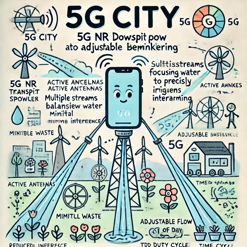
In NR, transmit power planning must consider beamforming gains and antenna configurations. 5G NR Downlink Transmit Power planning ensures compliance with national regulations on maximum Effective Isotropic Radiated Power (EIRP) while optimizing coverage and minimizing interference. For passive antenna systems, EIRP is calculated by combining transmit power, antenna gain, and losses, scaled by the number of transmit paths (e.g., 3 dB for 2x2 MIMO). For active antennas with beamforming, EIRP depends on beamforming weights and directional antenna gain, allowing higher efficiency despite lower per-path power. Unlike LTE, NR leverages active antennas to focus power into narrower beams, reducing intercell interference and improving system performance. However, power sharing across multiple simultaneous beams can lower per-beam transmit power. In TDD systems, duty cycles can further adjust average EIRP calculations, balancing power usage across downlink and uplink slots. These methods highlight the flexibility of NR’s transmit power management compared to LTE’s simpler, less adaptive configurations. [In a Nutshell: 5G NR optimizes transmit power by using beamforming and flexible EIRP management, offering advanced configurations compared to LTE.]
![]() Imagine LTE City and 5G City as towns with water sprinklers providing water (transmit power) to gardens (users). In LTE City, the sprinklers (passive antennas) spray water broadly, covering large areas evenly, but without much precision. In 5G City, the sprinklers are advanced and adjustable (active antennas). They can focus water into narrow streams, delivering it directly to the plants that need it most (beamforming), while using less water overall. This precise watering reduces waste (interference) and ensures every garden gets just the right amount. However, when several streams are used simultaneously, each stream delivers slightly less water to maintain balance. Additionally, the sprinklers in 5G City can adjust their flow rate depending on the time of day (TDD duty cycles), saving water during less busy periods. This smart system makes 5G City far more efficient and adaptable than LTE City. [In a Nutshell: 5G City uses advanced sprinklers (antennas) to focus water (power) where it’s needed, reducing waste and adapting to demand better than LTE City.]
Imagine LTE City and 5G City as towns with water sprinklers providing water (transmit power) to gardens (users). In LTE City, the sprinklers (passive antennas) spray water broadly, covering large areas evenly, but without much precision. In 5G City, the sprinklers are advanced and adjustable (active antennas). They can focus water into narrow streams, delivering it directly to the plants that need it most (beamforming), while using less water overall. This precise watering reduces waste (interference) and ensures every garden gets just the right amount. However, when several streams are used simultaneously, each stream delivers slightly less water to maintain balance. Additionally, the sprinklers in 5G City can adjust their flow rate depending on the time of day (TDD duty cycles), saving water during less busy periods. This smart system makes 5G City far more efficient and adaptable than LTE City. [In a Nutshell: 5G City uses advanced sprinklers (antennas) to focus water (power) where it’s needed, reducing waste and adapting to demand better than LTE City.]
- Search Forum 5G NR Downlink Transmit Power
PCI Allocation
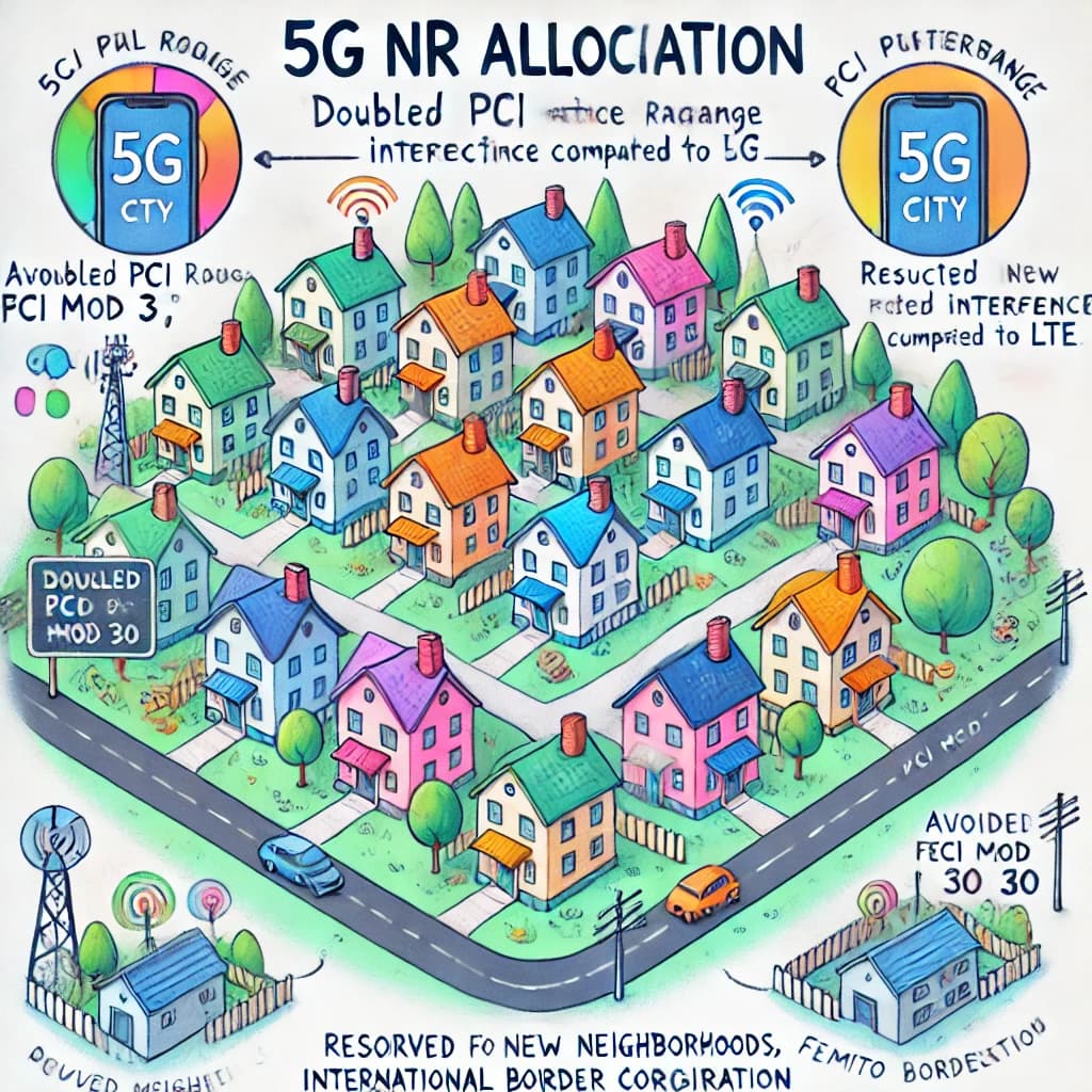
Physical Cell Identity (PCI) allocation in NR prevents collisions and confusion among neighboring cells. PCI (Physical layer Cell Identity) Allocation ensures efficient network performance and prevents interference. NR has 1008 PCIs, doubling LTE’s 504, which simplifies planning by increasing reuse distance and reducing PCI collisions in dense deployments. Like LTE, PCI planning must ensure networks are Collision Free (no overlapping PCI signals in a cell’s coverage) and Confusion Free (clear mapping of PCIs to cells). NR introduces additional rules, such as avoiding identical ‘PCI mod 3’, ‘PCI mod 4’, and ‘PCI mod 30’ values between neighboring cells to mitigate interference in synchronization signals and reference signals. Practical deployment complexities, like heterogeneous networks and irregular layouts, often challenge ideal PCI allocation. Additional considerations include reserving PCI ranges for future expansion or femto cells and addressing international border interference through regulatory coordination. These measures ensure robust, interference-free 5G operations while supporting advanced deployments. [In a Nutshell: NR’s PCI allocation expands on LTE, doubling PCIs and adding rules to reduce interference and support complex deployments.]
![]() Imagine LTE City and 5G City as towns with house numbers (PCIs) to identify homes (cells). In LTE City, there are fewer house numbers available, so planners must carefully space out homes with the same number to avoid confusion or mail mix-ups (interference). In 5G City, there are twice as many house numbers, making it easier to assign unique ones and reduce mix-ups, even in crowded neighborhoods (dense deployments). However, 5G City has stricter rules, like avoiding numbers that look too similar in certain ways (PCI mod 3, mod 4, mod 30), to ensure clear identification. Planners also reserve extra numbers for new neighborhoods (femto cells) and work with neighboring towns (international borders) to prevent duplicate addresses. This advanced system keeps 5G City organized and interference-free, even in complex setups, compared to LTE City. [In a Nutshell: 5G City’s PCI system doubles address options and adds strict rules to avoid confusion, making it more efficient than LTE City’s simpler system.]
Imagine LTE City and 5G City as towns with house numbers (PCIs) to identify homes (cells). In LTE City, there are fewer house numbers available, so planners must carefully space out homes with the same number to avoid confusion or mail mix-ups (interference). In 5G City, there are twice as many house numbers, making it easier to assign unique ones and reduce mix-ups, even in crowded neighborhoods (dense deployments). However, 5G City has stricter rules, like avoiding numbers that look too similar in certain ways (PCI mod 3, mod 4, mod 30), to ensure clear identification. Planners also reserve extra numbers for new neighborhoods (femto cells) and work with neighboring towns (international borders) to prevent duplicate addresses. This advanced system keeps 5G City organized and interference-free, even in complex setups, compared to LTE City. [In a Nutshell: 5G City’s PCI system doubles address options and adds strict rules to avoid confusion, making it more efficient than LTE City’s simpler system.]
- Search Forum 5G NR PCI Allocation
Cyclic Prefix
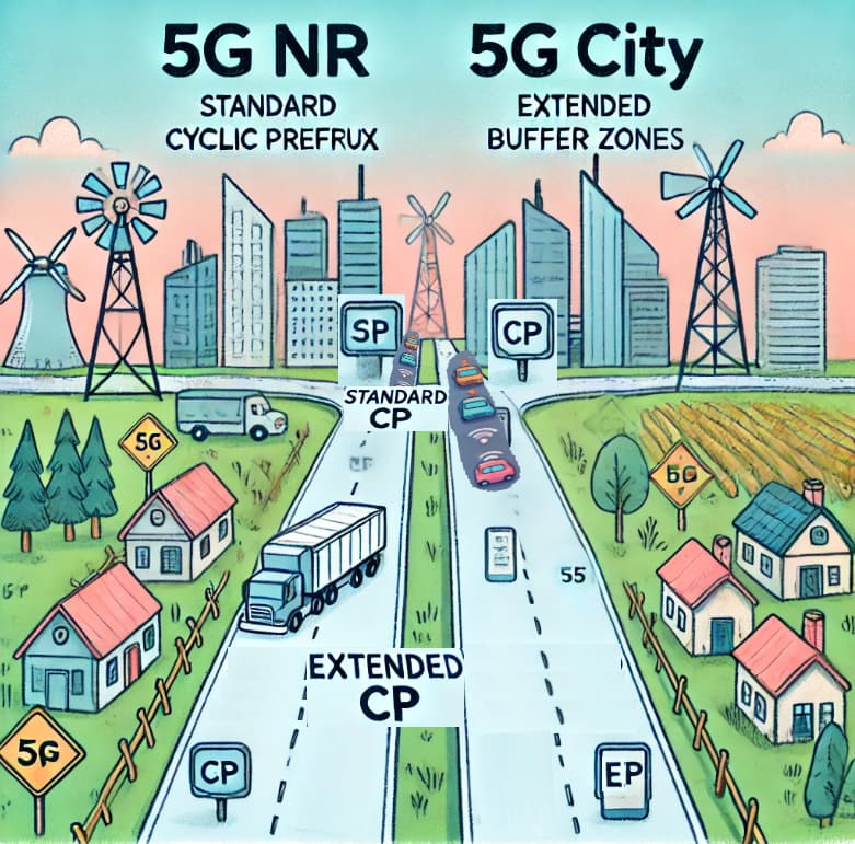
In 5G NR, the Cyclic Prefix (CP) acts as a guard period at the start of each symbol, protecting against multi-path delay spread while adding overhead to air-interface capacity. NR specifies both a normal cyclic prefix, suitable for most deployments, and an extended cyclic prefix, used primarily with 60 kHz subcarrier spacing in both Frequency Ranges 1 and 2. The extended CP increases symbol duration and reduces the number of symbols per slot from 14 to 12, lowering capacity but accommodating larger delay spreads. Deployment decisions for CP depend on factors like cell range and propagation environment. Smaller cells with minimal delay spreads (10–100 ns) typically use the normal CP, while macrocells in rural or urban environments may adjust based on delay spread and subcarrier spacing. Compared to LTE, NR retains similar CP functionality but offers enhanced flexibility for diverse deployment scenarios. [In a Nutshell: Cyclic Prefix in 5G NR balances delay protection and air capacity, offering flexible options for varied deployments compared to LTE.]
![]() Imagine LTE City and 5G City as towns with highways (data transmission) that occasionally encounter traffic jams (multi-path delay spread). In LTE City, all highways have the same small buffer zones (cyclic prefixes) to manage traffic delays, which works fine for most situations. In 5G City, highways can be built with either standard buffer zones (normal CP) for smooth, short routes in small neighborhoods or extended buffer zones (extended CP) for longer, busier routes in rural or large urban areas. The extended zones take up more road space (fewer symbols per slot) but ensure traffic flows smoothly despite heavy congestion. This flexibility allows 5G City to handle different traffic conditions better than LTE City, ensuring efficient and reliable transportation across all areas. [In a Nutshell: 5G City adjusts buffer zones (cyclic prefixes) for highways to ensure smooth traffic, offering more flexibility than LTE City.]
Imagine LTE City and 5G City as towns with highways (data transmission) that occasionally encounter traffic jams (multi-path delay spread). In LTE City, all highways have the same small buffer zones (cyclic prefixes) to manage traffic delays, which works fine for most situations. In 5G City, highways can be built with either standard buffer zones (normal CP) for smooth, short routes in small neighborhoods or extended buffer zones (extended CP) for longer, busier routes in rural or large urban areas. The extended zones take up more road space (fewer symbols per slot) but ensure traffic flows smoothly despite heavy congestion. This flexibility allows 5G City to handle different traffic conditions better than LTE City, ensuring efficient and reliable transportation across all areas. [In a Nutshell: 5G City adjusts buffer zones (cyclic prefixes) for highways to ensure smooth traffic, offering more flexibility than LTE City.]
- Search Forum 5G NR Cyclic Prefix
CSI Reference Signal
In 5G NR, the CSI Reference Signal (CSI-RS) is a versatile signal supporting various use cases, such as beam management and channel quality measurement. Planning for CSI-RS depends on network implementation and specific use cases, such as aiding beam refinement during beam management’s “P-2” phase. CSI-RS densities can be configured at 3, 1, or 0.5 Resource Elements per Resource Block (RE/RB), balancing measurement accuracy and frequency multiplexing. Higher densities, like 3 RE/RB, improve measurement accuracy and are suitable for Base Stations with 3–4 sectors, minimizing inter-sector interference through frequency multiplexing. For Base Stations with more than 4 sectors, densities of 1 RE/RB allow for increased multiplexing positions, optimizing resource usage in dense deployments. Compared to LTE, NR’s CSI-RS offers greater flexibility, supporting advanced features like beamforming and precise channel state information. [In a Nutshell: CSI-RS balances measurement accuracy and multiplexing to optimize resource usage and support advanced features like beamforming in 5G NR.]
![]() Imagine LTE City and 5G City as towns with weather stations (CSI-RS) that provide information to help manage traffic and plan new routes (beamforming and channel quality measurement). In LTE City, the stations are basic and less flexible, giving only general updates. In 5G City, the stations are highly advanced and can adjust their reporting frequency depending on the area’s needs. Busy intersections (Base Stations with 3–4 sectors) use frequent updates (high density like 3 RE/RB) for accurate traffic monitoring, while quieter neighborhoods (more than 4 sectors) spread out the updates (lower density like 1 RE/RB) to cover more areas efficiently. This smart system allows 5G City to manage resources and optimize routes far better than LTE City, making transportation smoother and more precise. [In a Nutshell: CSI-RS in 5G City acts like advanced weather stations, optimizing resources for smoother and more precise operations compared to LTE City.]
Imagine LTE City and 5G City as towns with weather stations (CSI-RS) that provide information to help manage traffic and plan new routes (beamforming and channel quality measurement). In LTE City, the stations are basic and less flexible, giving only general updates. In 5G City, the stations are highly advanced and can adjust their reporting frequency depending on the area’s needs. Busy intersections (Base Stations with 3–4 sectors) use frequent updates (high density like 3 RE/RB) for accurate traffic monitoring, while quieter neighborhoods (more than 4 sectors) spread out the updates (lower density like 1 RE/RB) to cover more areas efficiently. This smart system allows 5G City to manage resources and optimize routes far better than LTE City, making transportation smoother and more precise. [In a Nutshell: CSI-RS in 5G City acts like advanced weather stations, optimizing resources for smoother and more precise operations compared to LTE City.]
- Search Forum 5G NR CSI Reference Signal
Phase Tracking Reference Signal
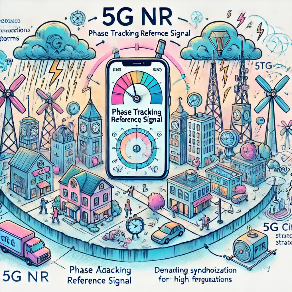
In 5G NR, the Phase Tracking Reference Signal (PTRS) supports phase noise compensation, ensuring high modulation accuracy and link reliability in challenging conditions like high frequencies or large bandwidths. PTRS can be configured for specific subcarriers, and careful planning is needed to minimize interference between neighboring cells. Different resourceElementOffset values and frequency multiplexing strategies can help avoid PTRS-to-PTRS interference, particularly between sectors of the same Base Station. PTRS aligns with the Demodulation Reference Signal (DMRS) subcarriers, but its reuse pattern is limited, potentially leading to some interference in dense deployments. PTRS is dynamically assigned to Resource Blocks based on UE-specific calculations, reducing interference through randomized offsets. Unlike LTE, which does not include PTRS, this signal is unique to NR, addressing the higher precision needs of 5G deployments. [In a Nutshell: PTRS in 5G NR ensures precise and reliable communication under challenging conditions, unlike LTE, which lacks this feature.]
![]() Imagine LTE City and 5G City as towns with clocks (signals) keeping everything synchronized. In LTE City, the clocks are basic and sometimes struggle to stay accurate during storms (high frequencies or large bandwidths). In 5G City, there’s a special team of clock adjusters (PTRS) who ensure the clocks remain precise, even in bad weather. They carefully place themselves around town (subcarriers) to avoid overlapping with each other, using different positions (resourceElementOffset values) and strategies to minimize confusion. These adjusters work dynamically, fine-tuning their placement based on where they’re needed most. Unlike LTE City, which lacks this advanced system, 5G City’s clock adjusters ensure everything runs smoothly and accurately, even in the most challenging conditions. [In a Nutshell: 5G City’s advanced clock adjusters (PTRS) ensure synchronization in tough situations, unlike LTE City, which lacks this feature.]
Imagine LTE City and 5G City as towns with clocks (signals) keeping everything synchronized. In LTE City, the clocks are basic and sometimes struggle to stay accurate during storms (high frequencies or large bandwidths). In 5G City, there’s a special team of clock adjusters (PTRS) who ensure the clocks remain precise, even in bad weather. They carefully place themselves around town (subcarriers) to avoid overlapping with each other, using different positions (resourceElementOffset values) and strategies to minimize confusion. These adjusters work dynamically, fine-tuning their placement based on where they’re needed most. Unlike LTE City, which lacks this advanced system, 5G City’s clock adjusters ensure everything runs smoothly and accurately, even in the most challenging conditions. [In a Nutshell: 5G City’s advanced clock adjusters (PTRS) ensure synchronization in tough situations, unlike LTE City, which lacks this feature.]
- Search Forum 5G NR Phase Tracking Reference Signal
PRACH Planning
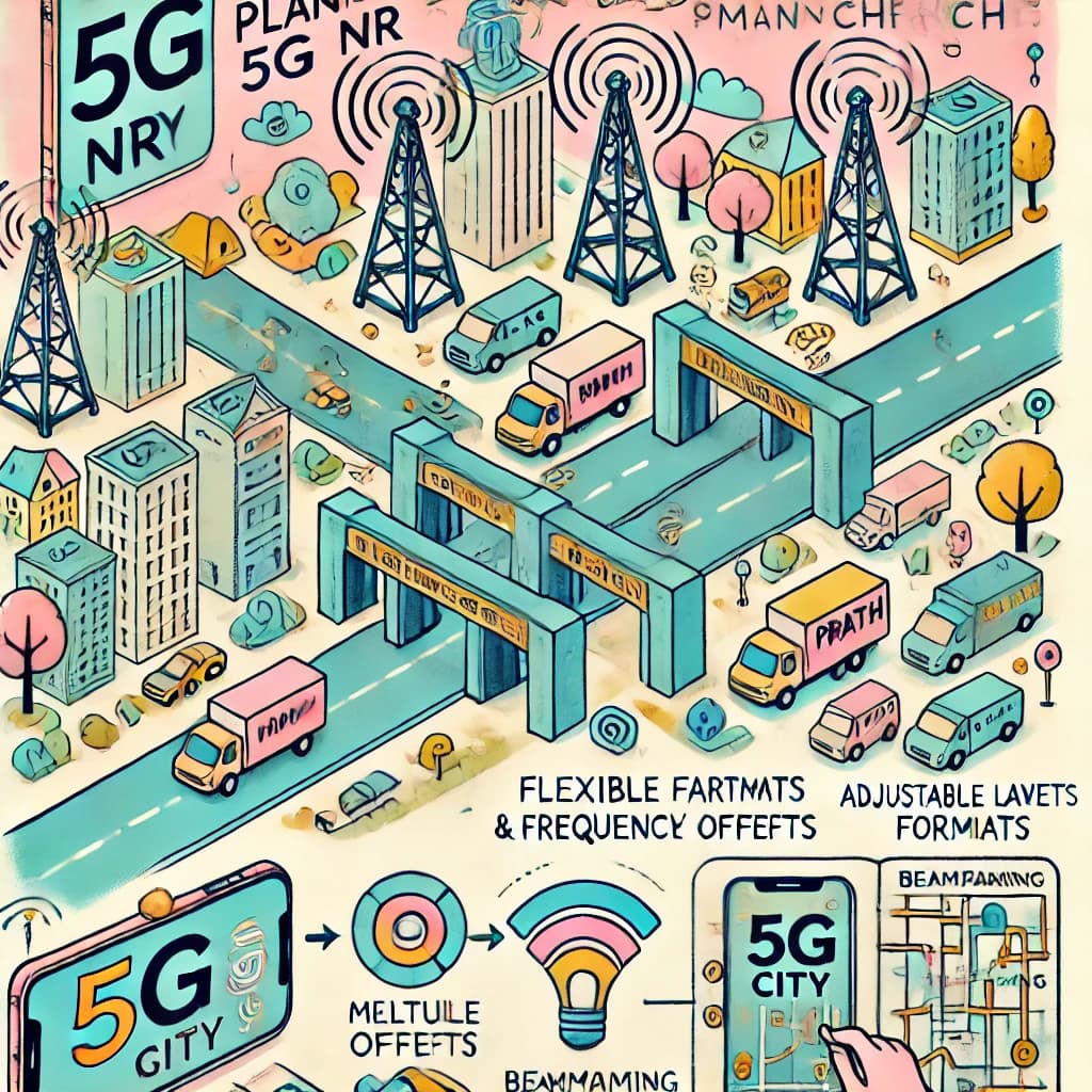
The Physical Random Access Channel (PRACH) in 5G NR facilitates initial access and synchronization. While LTE also utilized PRACH, NR enhances its capabilities with advanced planning parameters, including support for beamforming, multiple frequency offsets, and a wider range of formats. These enhancements enable NR to adapt to diverse deployment scenarios, providing greater flexibility and efficiency in network planning and operation. [In a Nutshell: 5G NR’s PRACH adds advanced features like beamforming and flexible formats for better adaptability and efficiency compared to LTE.]
![]() Imagine LTE City and 5G City as towns with gates (PRACH) that visitors use to enter. In LTE City, the gates are simple and work the same way everywhere, but in 5G City, the gates are smarter and more flexible. They can adjust their layout (formats), direct people through multiple lanes (frequency offsets), and even use spotlights (beamforming) to guide visitors more efficiently. These advanced gates help 5G City manage traffic better, adapt to busy or unique areas, and ensure everyone gets in smoothly, making it far more versatile than LTE City. [In a Nutshell: 5G City’s gates (PRACH) are smarter and more adaptable than LTE’s, using beamforming and flexible formats to handle traffic efficiently.]
Imagine LTE City and 5G City as towns with gates (PRACH) that visitors use to enter. In LTE City, the gates are simple and work the same way everywhere, but in 5G City, the gates are smarter and more flexible. They can adjust their layout (formats), direct people through multiple lanes (frequency offsets), and even use spotlights (beamforming) to guide visitors more efficiently. These advanced gates help 5G City manage traffic better, adapt to busy or unique areas, and ensure everyone gets in smoothly, making it far more versatile than LTE City. [In a Nutshell: 5G City’s gates (PRACH) are smarter and more adaptable than LTE’s, using beamforming and flexible formats to handle traffic efficiently.]
- Search Forum 5G NR PRACH Planning
PRACH Format
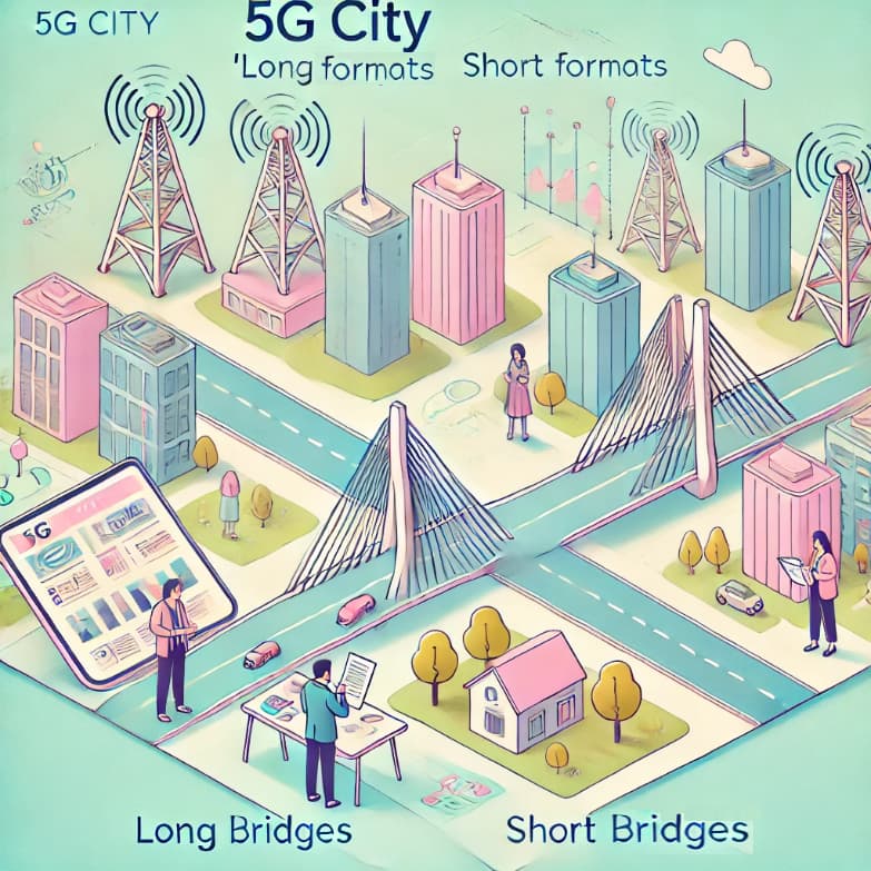
In 5G NR, the PRACH Format is chosen from long formats (0–3) or short formats (e.g., A1, B1, C0) to accommodate varying cell ranges and mobility requirements. Long PRACH Formats, suitable for Frequency Range 1, support extended cell ranges (up to 100 km) and are ideal for scenarios requiring robust coverage. In contrast, short PRACH Formats, mandatory for Frequency Range 2, support smaller cell ranges (up to 9.3 km) and are optimized for beamforming with large sweeping patterns and high mobility due to their shorter duration and higher subcarrier spacings. Selection factors include the Slot Format, which determines uplink transmission periods, and specific network requirements like coverage, latency, and mobility. For instance, short PRACH Formats excel in reducing latency and supporting advanced beam configurations, while long formats prioritize range and coverage. Unlike LTE, NR’s broader PRACH options address diverse deployment scenarios, ensuring optimal access and synchronization. [In a Nutshell: 5G PRACH Formats offer flexible options, with long formats for range and coverage and short formats for mobility and latency, surpassing LTE in adaptability.]
![]() Imagine LTE City and 5G City as towns with bridges (PRACH Formats) connecting neighborhoods. In LTE City, the bridges are uniform and only support short distances. In 5G City, there are two types of bridges: long ones (long formats) for faraway neighborhoods, ensuring everyone can cross even from a distance, and short ones (short formats) for nearby neighborhoods, designed for quick, efficient crossings with adjustable paths (beamforming). The long bridges are perfect for wide-open areas, while the short ones excel in busy, high-speed zones. This flexible bridge system in 5G City makes it easier to connect different parts of the town, adapting to various needs and improving access compared to LTE City. [In a Nutshell: 5G PRACH bridges connect neighborhoods efficiently, offering long bridges for range and short bridges for speed, surpassing LTE’s uniform approach.]
Imagine LTE City and 5G City as towns with bridges (PRACH Formats) connecting neighborhoods. In LTE City, the bridges are uniform and only support short distances. In 5G City, there are two types of bridges: long ones (long formats) for faraway neighborhoods, ensuring everyone can cross even from a distance, and short ones (short formats) for nearby neighborhoods, designed for quick, efficient crossings with adjustable paths (beamforming). The long bridges are perfect for wide-open areas, while the short ones excel in busy, high-speed zones. This flexible bridge system in 5G City makes it easier to connect different parts of the town, adapting to various needs and improving access compared to LTE City. [In a Nutshell: 5G PRACH bridges connect neighborhoods efficiently, offering long bridges for range and short bridges for speed, surpassing LTE’s uniform approach.]
- Search Forum 5G NR PRACH Format
PRACH Configuration Index
In 5G NR, the PRACH Configuration Index defines the timing and periodicity of PRACH (Physical Random Access Channel) opportunities, essential for initial access and synchronization. 3GPP specifies separate tables for Frequency Range 1 (paired and unpaired spectrum) and Frequency Range 2 (unpaired spectrum), each containing 256 rows grouped by PRACH Preamble Format. Selection begins by identifying the appropriate table and PRACH Preamble Format, followed by constraints imposed by the Slot Format in TDD deployments. For example, uplink availability in specific subframes restricts the choice of indices. The Configuration Index impacts capacity and latency trade-offs. Low indices provide minimal overhead but lower capacity and higher latency, while higher indices offer more frequent PRACH occasions for reduced latency at the cost of increased overhead. Additionally, the strategy for Root Sequence Index planning influences the choice, where indices can be allocated per Base Station or per cell to minimize Root Sequence collisions. This careful allocation ensures optimal use of time and frequency domains while balancing PRACH performance and network requirements. Compared to LTE, NR offers more flexible and granular PRACH configurations to address diverse deployment scenarios. [In a Nutshell: PRACH Configuration Index in NR balances timing, capacity, and latency, adapting flexibly for optimized synchronization and performance compared to LTE.]
![]() Imagine LTE City and 5G City as towns with train schedules (PRACH Configuration Index) to help visitors arrive on time. In LTE City, the schedules are simple, but in 5G City, the train schedules are flexible. There are different tables for local trains (Frequency Range 1) and high-speed trains (Frequency Range 2), each with many timing options. Frequent trains (high indices) make it easier for people to arrive quickly but require more resources, while longer gaps (low indices) save resources but can cause delays. The planners in 5G City carefully organize train routes to avoid collisions (Root Sequence Index conflicts). This advanced system ensures everyone reaches their destination efficiently, adapting to the city’s needs. [In a Nutshell: 5G City’s train schedules balance timing, resources, and collisions better than LTE City.]
Imagine LTE City and 5G City as towns with train schedules (PRACH Configuration Index) to help visitors arrive on time. In LTE City, the schedules are simple, but in 5G City, the train schedules are flexible. There are different tables for local trains (Frequency Range 1) and high-speed trains (Frequency Range 2), each with many timing options. Frequent trains (high indices) make it easier for people to arrive quickly but require more resources, while longer gaps (low indices) save resources but can cause delays. The planners in 5G City carefully organize train routes to avoid collisions (Root Sequence Index conflicts). This advanced system ensures everyone reaches their destination efficiently, adapting to the city’s needs. [In a Nutshell: 5G City’s train schedules balance timing, resources, and collisions better than LTE City.]
- Search Forum 5G NR PRACH Configuration Index
Zero Correlation Zone
The Zero Correlation Zone (ZCZ) prevents interference between PRACH sequences. In 5G NR, the ZCZ determines the cyclic shift used to generate PRACH preamble sequences from Root Sequences, affecting cell range and collision risk. A larger ZCZ enables greater cyclic shifts, supporting larger cell ranges but requiring more Root Sequences, which reduces the re-use pattern size and increases the risk of collisions. A smaller ZCZ allows more preamble sequences per Root Sequence, reducing the Root Sequence requirement and collision risk but limiting cell range. Selection depends on PRACH Preamble Format, subcarrier spacing, and mobility requirements, ensuring the chosen ZCZ meets the maximum cell range while maximizing Root Sequence re-use. For high-mobility scenarios, restricted cyclic shifts are applied using the High-Speed Flag. Careful planning prevents PRACH failures caused by delays exceeding the range, ensuring efficient random access procedures. Compared to LTE, NR’s ZCZ offers enhanced flexibility for diverse deployments. [In a Nutshell: ZCZ balances interference, range, and collision risks, offering 5G NR more deployment flexibility than LTE.]
![]() Imagine LTE City and 5G City as towns with echo-proof concert halls (Zero Correlation Zones) where performers use microphones (PRACH sequences) to avoid overlapping sounds. In LTE City, the halls are all the same size, handling only basic needs. In 5G City, the halls come in different sizes. Larger halls (larger ZCZ) keep echoes from interfering over longer distances (larger cell ranges), but fewer performances (Root Sequences) can fit in the space, requiring more halls for different performers. Smaller halls (smaller ZCZ) fit more performances but can only handle nearby audiences (smaller cell ranges). The planners carefully choose the right hall size based on the type of performance, audience distance, and expected noise levels (mobility and subcarrier spacing). This system ensures smooth, interference-free shows, making 5G City much more versatile than LTE City in handling diverse performance needs. [In a Nutshell: Zero Correlation Zones in 5G prevent interference by carefully balancing cell range and sequence re-use based on deployment needs.]
Imagine LTE City and 5G City as towns with echo-proof concert halls (Zero Correlation Zones) where performers use microphones (PRACH sequences) to avoid overlapping sounds. In LTE City, the halls are all the same size, handling only basic needs. In 5G City, the halls come in different sizes. Larger halls (larger ZCZ) keep echoes from interfering over longer distances (larger cell ranges), but fewer performances (Root Sequences) can fit in the space, requiring more halls for different performers. Smaller halls (smaller ZCZ) fit more performances but can only handle nearby audiences (smaller cell ranges). The planners carefully choose the right hall size based on the type of performance, audience distance, and expected noise levels (mobility and subcarrier spacing). This system ensures smooth, interference-free shows, making 5G City much more versatile than LTE City in handling diverse performance needs. [In a Nutshell: Zero Correlation Zones in 5G prevent interference by carefully balancing cell range and sequence re-use based on deployment needs.]
- Search Forum 5G NR Zero Correlation Zone
High-Speed Flag
In 5G NR, the High Speed Flag optimizes PRACH configurations for UEs with varying mobility levels by selecting between unrestricted and restricted cyclic shifts. Applicable only to long PRACH Formats in Frequency Range 1, it is configured via the restrictedSetConfig information element with options for unrestrictedSet (low/medium mobility), restrictedSetTypeA (high mobility), and restrictedSetTypeB (very high mobility). When set to true, the flag activates restricted cyclic shifts to enhance tolerance to Doppler frequency offsets caused by high mobility, reducing the number of preambles per Root Sequence but ensuring clear signal identification by avoiding unwanted peaks in the auto-correlation function. Conversely, when set to false, it uses unrestricted cyclic shifts, maximizing the number of preambles for low or medium mobility scenarios where Doppler effects are minimal. Restricted sets improve performance in high-speed scenarios but increase complexity in Root Sequence allocation due to reduced re-use pattern size. For small cells or indoor deployments, the flag is typically false, while it is set to true for macro cells serving high-speed UEs. This feature ensures efficient random access tailored to deployment needs and mobility conditions, addressing challenges unique to 5G NR and offering flexibility not present in LTE. [In a Nutshell: The High Speed Flag balances PRACH configurations for mobility, enabling efficient random access for both slow and fast UEs in 5G NR.]
![]() Imagine LTE City and 5G City as towns with traffic lights (High-Speed Flag) controlling vehicles (UEs) on busy roads (PRACH configurations). In LTE City, the lights work the same way for all speeds, which can lead to confusion for fast-moving vehicles. In 5G City, the traffic lights are smarter. When set to normal mode (flag is false), they allow more vehicles to pass through (unrestricted cyclic shifts), perfect for slow or moderate speeds. When set to high-speed mode (flag is true), the lights adjust to manage fast vehicles (restricted cyclic shifts), ensuring they don’t miss their turn or cause jams (unwanted signal peaks). High-speed mode handles challenging highways (macro cells with high mobility), while normal mode is ideal for quieter streets (small cells or indoor setups). This adaptive system makes 5G City much better at managing diverse traffic conditions compared to LTE City. [In a Nutshell: The High-Speed Flag in 5G adapts traffic lights for vehicles moving at different speeds, ensuring smooth and efficient flow for all conditions.]
Imagine LTE City and 5G City as towns with traffic lights (High-Speed Flag) controlling vehicles (UEs) on busy roads (PRACH configurations). In LTE City, the lights work the same way for all speeds, which can lead to confusion for fast-moving vehicles. In 5G City, the traffic lights are smarter. When set to normal mode (flag is false), they allow more vehicles to pass through (unrestricted cyclic shifts), perfect for slow or moderate speeds. When set to high-speed mode (flag is true), the lights adjust to manage fast vehicles (restricted cyclic shifts), ensuring they don’t miss their turn or cause jams (unwanted signal peaks). High-speed mode handles challenging highways (macro cells with high mobility), while normal mode is ideal for quieter streets (small cells or indoor setups). This adaptive system makes 5G City much better at managing diverse traffic conditions compared to LTE City. [In a Nutshell: The High-Speed Flag in 5G adapts traffic lights for vehicles moving at different speeds, ensuring smooth and efficient flow for all conditions.]
- Search Forum 5G NR High-Speed Flag
Root Sequence Index
In 5G NR, the Root Sequence Index defines the sequences used to generate the 64 PRACH preambles for each PRACH occasion. The number of Root Sequences required per cell depends on the Zero Correlation Zone, with larger zones reducing the number of preambles generated per sequence and increasing the Root Sequence requirement. The first Root Sequence for a cell is specified via the prach-RootSequenceIndex in the RACH-ConfigCommon parameter, broadcast in SIB1 or provided through dedicated signaling, with additional sequences allocated consecutively as logical indices. Logical Root Sequences are mapped to physical sequences via a 3GPP-defined lookup table. Proper allocation ensures sufficient reuse distance to prevent collisions, which can lead to increased PRACH load and poor performance, such as multiple cells responding to the same preamble and causing unnecessary signaling failures. Careful planning minimizes these issues, ensuring efficient PRACH operation in live deployments. Compared to LTE, NR’s Root Sequence Index planning accommodates more dynamic and scalable network configurations. [In a Nutshell: Root Sequence Index planning ensures PRACH efficiency by avoiding collisions and accommodating scalable deployments in 5G NR.]
![]() Imagine LTE City and 5G City as towns with water fountains (Root Sequences) where people fill their bottles (PRACH preambles). In LTE City, the fountains are fewer and simpler, often leading to crowding. In 5G City, planners carefully assign fountains to different neighborhoods based on the size of the area (Zero Correlation Zone). Larger areas need more fountains since each one serves fewer people, while smaller areas can reuse fountains more efficiently. Each fountain has a specific label (RootSequenceIndex) that tells visitors which one to use, and these labels are shared via announcements (SIB1 or dedicated signals). The planners ensure that no two neighborhoods use the same fountain for the same group of visitors, avoiding mix-ups (collisions). This organized system makes 5G City’s fountains more efficient and scalable, accommodating the needs of both small and large communities better than LTE City. [In a Nutshell: Root Sequences in 5G City are carefully planned to prevent collisions and improve efficiency compared to LTE City.]
Imagine LTE City and 5G City as towns with water fountains (Root Sequences) where people fill their bottles (PRACH preambles). In LTE City, the fountains are fewer and simpler, often leading to crowding. In 5G City, planners carefully assign fountains to different neighborhoods based on the size of the area (Zero Correlation Zone). Larger areas need more fountains since each one serves fewer people, while smaller areas can reuse fountains more efficiently. Each fountain has a specific label (RootSequenceIndex) that tells visitors which one to use, and these labels are shared via announcements (SIB1 or dedicated signals). The planners ensure that no two neighborhoods use the same fountain for the same group of visitors, avoiding mix-ups (collisions). This organized system makes 5G City’s fountains more efficient and scalable, accommodating the needs of both small and large communities better than LTE City. [In a Nutshell: Root Sequences in 5G City are carefully planned to prevent collisions and improve efficiency compared to LTE City.]
- Search Forum 5G NR Root Sequence Index
PRACH Frequency Offset
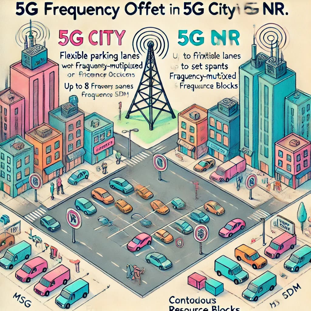
In 5G NR, the PRACH Frequency Offset determines the placement of PRACH occasions in the frequency domain, with options to configure a single PRACH occasion or up to 8 frequency-multiplexed occasions within a contiguous set of Resource Blocks. This configuration is specified using the msg1-FrequencyStart (first Resource Block) and msg1-FDM (number of PRACH occasions) information elements, provided via SIB1 or dedicated signaling. PRACH frequency offset planning aims to avoid fragmentation of Resource Blocks allocated to the PUSCH, as contiguous allocation ensures optimal resource usage. While contiguous Resource Blocks are mandatory for PUSCH in Frequency Range 2 and Frequency Range 1 with Transform Precoding (DFT-S-OFDM), non-contiguous blocks may be used in Frequency Range 1 with CP-OFDM, provided they meet specific criteria. Proper PRACH frequency offset configuration supports efficient uplink scheduling and minimizes interference, ensuring reliable initial access and synchronization. Compared to LTE, NR’s flexibility in PRACH frequency configuration supports advanced deployment scenarios with greater resource optimization. [In a Nutshell: 5G NR optimizes PRACH frequency placement for efficient scheduling, avoiding fragmentation, and supporting diverse deployment needs.]
![]() Imagine LTE City and 5G City as towns with parking spaces (PRACH frequency offsets) for visitors. In LTE City, parking spots are simple and fixed, with limited flexibility. In 5G City, planners can arrange parking in single rows or multiple lanes (up to 8 frequency-multiplexed occasions) to fit more cars efficiently in the same area. Each lane starts at a specific spot (msg1-FrequencyStart) and spans a set number of spaces (msg1-FDM). To keep traffic flowing smoothly, planners make sure parking areas don’t block the main roads (PUSCH Resource Blocks), keeping them contiguous for easy access. In some cases, the city allows slightly separated parking spots (non-contiguous blocks), but only if they follow strict rules to prevent congestion. This smart parking system makes 5G City more adaptable and resource-efficient, ensuring smooth entry for everyone, even in busy areas, far surpassing LTE City’s simpler setup. [In a Nutshell: 5G NR’s flexible parking system (PRACH offsets) ensures smooth and efficient visitor management, unlike LTE’s fixed approach.]
Imagine LTE City and 5G City as towns with parking spaces (PRACH frequency offsets) for visitors. In LTE City, parking spots are simple and fixed, with limited flexibility. In 5G City, planners can arrange parking in single rows or multiple lanes (up to 8 frequency-multiplexed occasions) to fit more cars efficiently in the same area. Each lane starts at a specific spot (msg1-FrequencyStart) and spans a set number of spaces (msg1-FDM). To keep traffic flowing smoothly, planners make sure parking areas don’t block the main roads (PUSCH Resource Blocks), keeping them contiguous for easy access. In some cases, the city allows slightly separated parking spots (non-contiguous blocks), but only if they follow strict rules to prevent congestion. This smart parking system makes 5G City more adaptable and resource-efficient, ensuring smooth entry for everyone, even in busy areas, far surpassing LTE City’s simpler setup. [In a Nutshell: 5G NR’s flexible parking system (PRACH offsets) ensures smooth and efficient visitor management, unlike LTE’s fixed approach.]
- Search Forum 5G NR PRACH Frequency Offset
Neighbour Planning
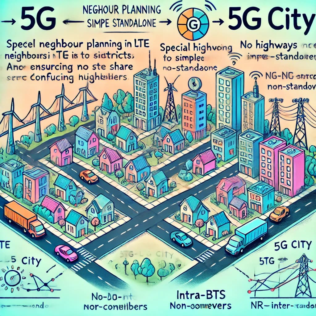
In 5G NR, Neighbour Planning ensures seamless mobility and efficient handovers by defining relationships between cells and Base Stations. While cell-specific neighbour definitions are unnecessary for cell reselection unless blacklisting or power offsets are required, they are critical for handovers and serving cell changes, particularly in EN-DC Non-Standalone Base Stations. Key configurations include LTE-to-NR neighbour relations for X2 connections, LTE-to-NR cell relations for EN-DC, and NR-to-NR neighbour relations for intra/inter-BTS operations. Additionally, LTE-to-LTE neighbour relations support handovers without new configurations if LTE’s neighbour plans are already in place. PCI checks are essential to avoid PCI collisions and confusion. Neighbour planning can use Self-Organising Network (SON) features, like Automatic Neighbour Relations (ANR), to reduce manual planning by leveraging UE measurement reports. However, in EN-DC setups, SON capabilities may be limited if NR Base Stations lack SIB1 broadcasts or MME connectivity. Compared to LTE, NR’s neighbour planning introduces enhanced configurations to support multi-standard networks and advanced deployment scenarios. [In a Nutshell: Neighbour planning in 5G NR ensures smooth handovers and mobility, using advanced configurations and SON features to handle multi-standard deployments.]
![]() Imagine LTE City and 5G City as towns with interconnected streets (neighbor relations) to ensure smooth travel for residents (users). In LTE City, the streets are well-planned for basic routes, but in 5G City, the roads are more advanced and designed to handle multiple modes of transport (LTE-to-NR and NR-to-NR handovers). Special highways connect LTE neighborhoods to 5G districts (EN-DC Non-Standalone), and thoroughfare connections link 5G-only areas (intra/inter-BTS NR operations). Planners ensure no two streets share the same confusing house numbers (PCI collisions) to keep travel orderly. In 5G City, smart systems (SON and ANR) help map out these connections automatically, but they sometimes need extra help for complex setups like EN-DC. This enhanced street network makes 5G City more efficient and adaptable for modern transportation needs than LTE City. [In a Nutshell: 5G City’s advanced and automated neighbor planning ensures seamless connections and smooth mobility for users.]
Imagine LTE City and 5G City as towns with interconnected streets (neighbor relations) to ensure smooth travel for residents (users). In LTE City, the streets are well-planned for basic routes, but in 5G City, the roads are more advanced and designed to handle multiple modes of transport (LTE-to-NR and NR-to-NR handovers). Special highways connect LTE neighborhoods to 5G districts (EN-DC Non-Standalone), and thoroughfare connections link 5G-only areas (intra/inter-BTS NR operations). Planners ensure no two streets share the same confusing house numbers (PCI collisions) to keep travel orderly. In 5G City, smart systems (SON and ANR) help map out these connections automatically, but they sometimes need extra help for complex setups like EN-DC. This enhanced street network makes 5G City more efficient and adaptable for modern transportation needs than LTE City. [In a Nutshell: 5G City’s advanced and automated neighbor planning ensures seamless connections and smooth mobility for users.]
- Search Forum 5G NR Neighbour Planning
Cell & BTS Identity Planning
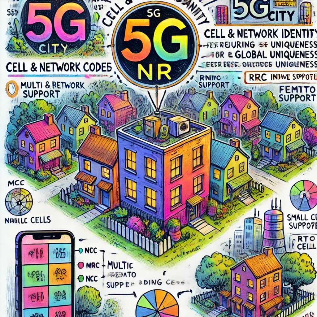
In 5G NR, Cell and BTS Identity Planning uses the NR Cell Global Identity (NCGI), combining the Mobile Country Code (MCC), Mobile Network Code (MNC), and NR Cell Identity (NCI) to uniquely identify cells globally. The NCI consists of 36 bits, shared between the gNB Identity (22–32 bits) and the Cell Identity (4–14 bits). Allocating 22 bits for the gNB Identity supports up to 4,194,304 values, sufficient for most networks but expandable for dense deployments like small or femto cells. For efficient RRC Inactive state management, using 16 bits for the gNB Identity within the I-RNTI avoids additional Base Station identity planning. The remaining bits in the NCI allow flexible cell identification, supporting up to 16,383 cells per gNB, which is beneficial in CU/DU Split architectures with high cell densities. The MCC, MNC, and NCI are broadcast via SIB1, enabling multi-PLMN support and independent Cell Identity planning for network sharing. Compared to LTE, NR offers enhanced scalability and flexibility for diverse deployment scenarios. [In a Nutshell: 5G NR’s cell and BTS identity planning ensures global uniqueness, scalability, and adaptability for modern networks.]
![]() Imagine LTE City and 5G City as towns with unique addresses (NCGI) for every building (cell). In LTE City, the address system is basic and works well for smaller neighborhoods. In 5G City, the address system is far more advanced, using a combination of country codes (MCC), network codes (MNC), and building numbers (NCI) to ensure every building is globally unique. Each neighborhood (gNB) gets a set of address ranges, with enough space for millions of buildings, accommodating even densely packed areas like apartment complexes (small cells or femto cells). The flexible address system also makes it easy to manage shared spaces (multi-PLMN support) and special zones for less active residents (RRC Inactive state). This scalable and efficient addressing system ensures that 5G City is ready for growth and complexity, outperforming LTE City’s simpler approach. [In a Nutshell: 5G City’s advanced addressing ensures global uniqueness and scalability, surpassing LTE City’s system.]
Imagine LTE City and 5G City as towns with unique addresses (NCGI) for every building (cell). In LTE City, the address system is basic and works well for smaller neighborhoods. In 5G City, the address system is far more advanced, using a combination of country codes (MCC), network codes (MNC), and building numbers (NCI) to ensure every building is globally unique. Each neighborhood (gNB) gets a set of address ranges, with enough space for millions of buildings, accommodating even densely packed areas like apartment complexes (small cells or femto cells). The flexible address system also makes it easy to manage shared spaces (multi-PLMN support) and special zones for less active residents (RRC Inactive state). This scalable and efficient addressing system ensures that 5G City is ready for growth and complexity, outperforming LTE City’s simpler approach. [In a Nutshell: 5G City’s advanced addressing ensures global uniqueness and scalability, surpassing LTE City’s system.]
- Search Forum 5G NR Cell & BTS Identity Planning
RAN Notification Area Planning
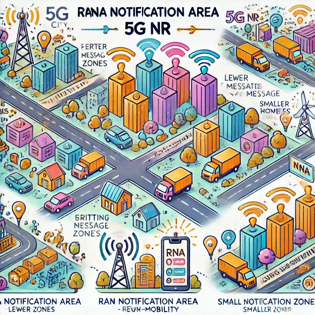
In 5G NR, RAN Notification Area (RNA) Planning is essential for enabling the RRC Inactive state, allowing UEs to move within an RNA without informing the network of serving cell changes. This reduces signaling load, as paging messages are broadcast across all cells in the RNA, and the Base Station retains the UE context. Larger RNAs reduce the need for RNA updates due to mobility, while smaller RNAs decrease paging load and require fewer Xn connections, especially in CU/DU Split architectures. RNAs can be configured as collections of Cell Identities or Tracking Area Code (TAC) and RAN Area Code (RAC) combinations. Planning should avoid RNA boundaries crossing high-mobility routes to minimize updates. The I-RNTI, used to identify UEs in the RRC Inactive state, incorporates Base Station identities. While 3GPP defines full (40-bit) and short (24-bit) I-RNTIs, allocation strategies depend on network implementation, with options to reuse bits from the gNB Identity within the NR Cell Identity. This flexibility ensures efficient resource utilization, with minimal message sizes for improved coverage performance. Compared to LTE, RNA planning introduces advanced mechanisms to enhance signaling efficiency and mobility management. [In a Nutshell: RNA planning optimizes signaling and mobility in 5G, enabling efficient paging and resource management, surpassing LTE’s capabilities.]
![]() Imagine LTE City and 5G City as towns with delivery zones (RAN Notification Areas) for packages (paging messages). In LTE City, every time someone moves, they must update their exact location, creating extra work for the delivery drivers. In 5G City, residents in an area can move freely within their zone (RNA) without notifying the network, reducing the need for constant updates. Larger zones mean fewer updates but require more effort to deliver messages to everyone, while smaller zones make deliveries quicker but increase update frequency. The planners carefully draw these zones to avoid splitting busy highways (high-mobility routes), ensuring smooth operations. Each package includes a tracking code (I-RNTI), which helps drivers know which zone it belongs to. This smart zoning system in 5G City improves efficiency and resource management, far surpassing LTE City’s simpler but less flexible approach. [In a Nutshell: 5G RNA zones reduce update needs, balance delivery efficiency, and manage mobility better than LTE.]
Imagine LTE City and 5G City as towns with delivery zones (RAN Notification Areas) for packages (paging messages). In LTE City, every time someone moves, they must update their exact location, creating extra work for the delivery drivers. In 5G City, residents in an area can move freely within their zone (RNA) without notifying the network, reducing the need for constant updates. Larger zones mean fewer updates but require more effort to deliver messages to everyone, while smaller zones make deliveries quicker but increase update frequency. The planners carefully draw these zones to avoid splitting busy highways (high-mobility routes), ensuring smooth operations. Each package includes a tracking code (I-RNTI), which helps drivers know which zone it belongs to. This smart zoning system in 5G City improves efficiency and resource management, far surpassing LTE City’s simpler but less flexible approach. [In a Nutshell: 5G RNA zones reduce update needs, balance delivery efficiency, and manage mobility better than LTE.]
- Search Forum 5G NR RAN Notification Area Planning
Tracking Area Planning
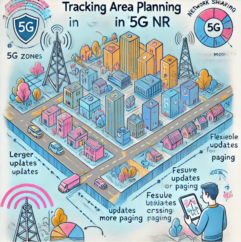
In 5G NR, Tracking Area Planning determines how UEs register and manage mobility while in RRC Idle mode. For Non-Standalone (EN-DC) architectures, UEs rely on LTE’s Tracking Areas, extracting the 4G Tracking Area Identity from LTE SIB1 and registering with the MME. For Standalone (SA) architectures, UEs use NR Tracking Areas from NR SIB1 and register with the AMF. A UE can receive a list of Tracking Area Identities, allowing it to roam without triggering frequent updates. 5G SIB1 supports up to 12 PLMNs with separate Tracking Area Codes (TACs) for each, offering flexibility for network sharing, compared to LTE’s earlier constraints. TACs are 24 bits, providing a large range of values, with specific codes reserved for deletion. Large Tracking Areas reduce signaling load by minimizing updates but increase paging loads, as all cells in the area may broadcast all paging messages. Solutions like hierarchical paging can reduce paging load by limiting the initial broadcast to the last connected cell, though this may increase latency for moving UEs. Dynamic planning, such as combining smaller Tracking Areas into lists, allows networks to balance paging and update signaling loads. New networks can start with larger Tracking Areas and split them as traffic grows, with boundaries avoiding high mobility routes. For 5G deployments over 4G, Tracking Area plans can be reused or offset for easier differentiation. Compared to LTE, 5G offers enhanced flexibility, scalability, and dynamic management for Tracking Area Planning. [In a Nutshell: 5G Tracking Area Planning balances updates and paging for efficient mobility, with flexibility and scalability far beyond LTE.]
![]() Imagine LTE City and 5G City as towns with zones (Tracking Areas) where residents check in with local offices (network registration). In LTE City, the zones are fixed, and residents must frequently update their location as they move between areas, creating extra paperwork. In 5G City, the zones are smarter and more flexible. Residents in certain areas (Standalone architecture) can roam freely within larger zones without constant check-ins, reducing updates but requiring more announcements (paging). To balance the load, 5G City uses clever techniques like starting with the last known office for messages (hierarchical paging) or dynamically adjusting zone sizes as the population grows. These zones can overlap for shared neighborhoods (network sharing), and planners ensure they avoid crossing busy highways (high-mobility routes) to minimize disruptions. This advanced system lets 5G City handle mobility and communication far more efficiently and flexibly than LTE City. [In a Nutshell: 5G City’s flexible zones reduce updates, balance paging, and handle mobility more effectively than LTE City.]
Imagine LTE City and 5G City as towns with zones (Tracking Areas) where residents check in with local offices (network registration). In LTE City, the zones are fixed, and residents must frequently update their location as they move between areas, creating extra paperwork. In 5G City, the zones are smarter and more flexible. Residents in certain areas (Standalone architecture) can roam freely within larger zones without constant check-ins, reducing updates but requiring more announcements (paging). To balance the load, 5G City uses clever techniques like starting with the last known office for messages (hierarchical paging) or dynamically adjusting zone sizes as the population grows. These zones can overlap for shared neighborhoods (network sharing), and planners ensure they avoid crossing busy highways (high-mobility routes) to minimize disruptions. This advanced system lets 5G City handle mobility and communication far more efficiently and flexibly than LTE City. [In a Nutshell: 5G City’s flexible zones reduce updates, balance paging, and handle mobility more effectively than LTE City.]
- Search Forum 5G NR Tracking Area Planning
Throughput Expectations
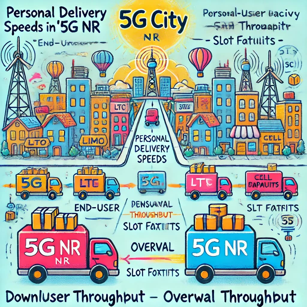
In 5G NR, Throughput Expectations involve estimating uplink and downlink throughputs to understand system performance and guide decisions, such as Transport Network bandwidth requirements. These estimates, categorized as end-user connection throughput and total cell throughput, depend on numerous variables, including UE and network capabilities (e.g., MIMO configuration), overheads (SS/PBCH, PRACH, Reference Signals), and Slot Format configurations. Throughputs can be calculated as maximums, averages, or percentiles, with averages requiring knowledge of radio conditions or simulations. For TDD systems, throughput calculations depend on the uplink/downlink Slot Format. For example, Slot Formats with downlink-heavy configurations allow some SS/PBCH Blocks and data transmissions to overlap, optimizing capacity but introducing latency trade-offs. Simulation models, based on generic or specific deployment scenarios, provide detailed insights, enabling better predictions and problem identification compared to LTE’s simpler estimation methods. [In a Nutshell: 5G NR throughput estimates improve system planning with advanced simulations and adaptable configurations beyond LTE’s capabilities.]
![]() Imagine LTE City and 5G City as towns with delivery services (throughput) for packages (data). In LTE City, the delivery system is basic, offering rough estimates of how many packages can be sent at once. In 5G City, the delivery system is much more advanced, calculating both personal delivery speeds (end-user throughput) and the town’s overall capacity (cell throughput). The system considers factors like how many trucks (MIMO configurations) and routes (Slot Formats) are available, as well as road conditions (radio environments). Some routes prioritize faster deliveries (downlink-heavy Slot Formats), while others balance between sending and receiving packages. Planners use simulations to predict traffic, identify bottlenecks, and optimize resources for different areas. This sophisticated system ensures 5G City delivers packages faster and more efficiently, meeting diverse needs far better than LTE City. [In a Nutshell: 5G City’s advanced delivery system ensures faster, more efficient data transport compared to LTE City.]
Imagine LTE City and 5G City as towns with delivery services (throughput) for packages (data). In LTE City, the delivery system is basic, offering rough estimates of how many packages can be sent at once. In 5G City, the delivery system is much more advanced, calculating both personal delivery speeds (end-user throughput) and the town’s overall capacity (cell throughput). The system considers factors like how many trucks (MIMO configurations) and routes (Slot Formats) are available, as well as road conditions (radio environments). Some routes prioritize faster deliveries (downlink-heavy Slot Formats), while others balance between sending and receiving packages. Planners use simulations to predict traffic, identify bottlenecks, and optimize resources for different areas. This sophisticated system ensures 5G City delivers packages faster and more efficiently, meeting diverse needs far better than LTE City. [In a Nutshell: 5G City’s advanced delivery system ensures faster, more efficient data transport compared to LTE City.]
- Search Forum 5G NR Throughput Expectations
Downlink Throughput
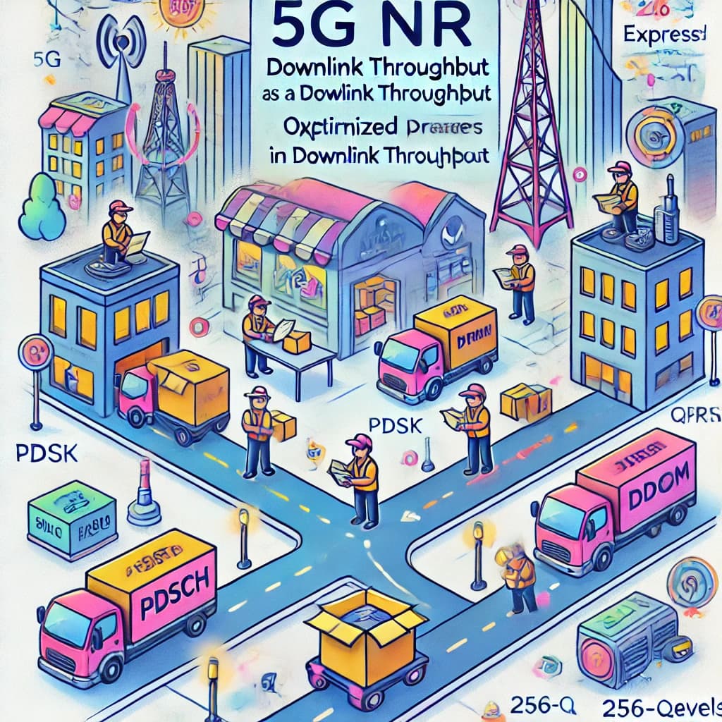
In 5G NR, Downlink Throughput is estimated by calculating the per-slot throughput and averaging over time, based on the number of symbols available for data transmission. For example, a typical slot allocates 12 symbols to the PDSCH, reserving one symbol each for the PDCCH and DMRS. High throughput can be achieved even under suboptimal conditions, such as 130 Mbps on a 100 MHz bandwidth using QPSK and a coding rate of 0.438. Throughput varies with Channel Quality Indicator (CQI) levels, ranging from QPSK (CQI 3) to 256-QAM (CQI 15) with respective coding rates. These calculations exclude overheads from CSI Reference Signals, Tracking Reference Signals, and Phase Tracking Reference Signals, assuming no additional DMRS symbols. This showcases 5G NR’s efficiency in achieving high downlink performance, often exceeding LTE capabilities in similar scenarios. [In a Nutshell: 5G NR’s advanced configurations deliver higher downlink speeds with optimized resource usage, outperforming LTE in many cases.]
![]() Imagine LTE City and 5G City as towns with package delivery centers (downlink throughput) handling shipments to residents. In LTE City, the center operates steadily but is limited in how quickly it can sort and send packages. In 5G City, the delivery center is highly optimized, with 12 workers (symbols for PDSCH) handling packages, while 2 others manage instructions and coordination (PDCCH and DMRS). Even during bad weather (suboptimal conditions), 5G City can still deliver over 130 packages (Mbps) using a robust delivery system (QPSK). Depending on the roads (Channel Quality Indicator levels), 5G City switches between basic routes (QPSK) and express highways (256-QAM), ensuring maximum efficiency. Unlike LTE City, 5G City’s advanced operations can handle more packages faster, with fewer delays, making it the go-to choice for high-speed deliveries. [In a Nutshell: 5G City’s delivery system is faster, more efficient, and adaptable, outperforming LTE City in all conditions.]
Imagine LTE City and 5G City as towns with package delivery centers (downlink throughput) handling shipments to residents. In LTE City, the center operates steadily but is limited in how quickly it can sort and send packages. In 5G City, the delivery center is highly optimized, with 12 workers (symbols for PDSCH) handling packages, while 2 others manage instructions and coordination (PDCCH and DMRS). Even during bad weather (suboptimal conditions), 5G City can still deliver over 130 packages (Mbps) using a robust delivery system (QPSK). Depending on the roads (Channel Quality Indicator levels), 5G City switches between basic routes (QPSK) and express highways (256-QAM), ensuring maximum efficiency. Unlike LTE City, 5G City’s advanced operations can handle more packages faster, with fewer delays, making it the go-to choice for high-speed deliveries. [In a Nutshell: 5G City’s delivery system is faster, more efficient, and adaptable, outperforming LTE City in all conditions.]
- Search Forum 5G NR Downlink Throughput
Uplink Throughput
In 5G NR, Uplink Throughput is estimated similarly to downlink throughput by calculating per-slot throughput and averaging over time. For an uplink data slot, 11 symbols are typically available for the PUSCH after reserving one symbol for the DMRS and two symbols for the SRS and PUCCH. This allocation results in slightly lower uplink throughput compared to downlink throughput, which has 12 symbols available for the PDSCH. The calculations assume no frequency multiplexing between the PUSCH and DMRS. Optional 256-QAM modulation, supported by the pusch-256QAM information element, can further enhance uplink throughput if both the UE and network support it. This approach underscores 5G NR’s capability to optimize uplink performance while accommodating advanced features like higher-order modulation. [In a Nutshell: 5G NR uplink delivers efficient performance with advanced symbol allocation and modulation options, even slightly less than downlink throughput.]
![]() Imagine LTE City and 5G City as towns with courier services (uplink throughput) where residents send packages to central hubs. In LTE City, the system is effective but has limits on how many packages can be sent at once. In 5G City, the courier service is more advanced. Each time slot has 11 couriers (symbols for PUSCH) actively delivering packages, while 3 others are reserved for coordination and tracking (DMRS, SRS, and PUCCH). Although slightly fewer couriers are available compared to the receiving service (downlink throughput), the process is still highly efficient. For special deliveries, the service can use faster vehicles (256-QAM modulation) if both the sender and the network are equipped for it. This system ensures 5G City’s uplink is optimized for speed and precision, outpacing LTE City’s capabilities. [In a Nutshell: 5G City’s uplink uses advanced courier coordination and fast vehicles to deliver packages efficiently and accurately.]
Imagine LTE City and 5G City as towns with courier services (uplink throughput) where residents send packages to central hubs. In LTE City, the system is effective but has limits on how many packages can be sent at once. In 5G City, the courier service is more advanced. Each time slot has 11 couriers (symbols for PUSCH) actively delivering packages, while 3 others are reserved for coordination and tracking (DMRS, SRS, and PUCCH). Although slightly fewer couriers are available compared to the receiving service (downlink throughput), the process is still highly efficient. For special deliveries, the service can use faster vehicles (256-QAM modulation) if both the sender and the network are equipped for it. This system ensures 5G City’s uplink is optimized for speed and precision, outpacing LTE City’s capabilities. [In a Nutshell: 5G City’s uplink uses advanced courier coordination and fast vehicles to deliver packages efficiently and accurately.]
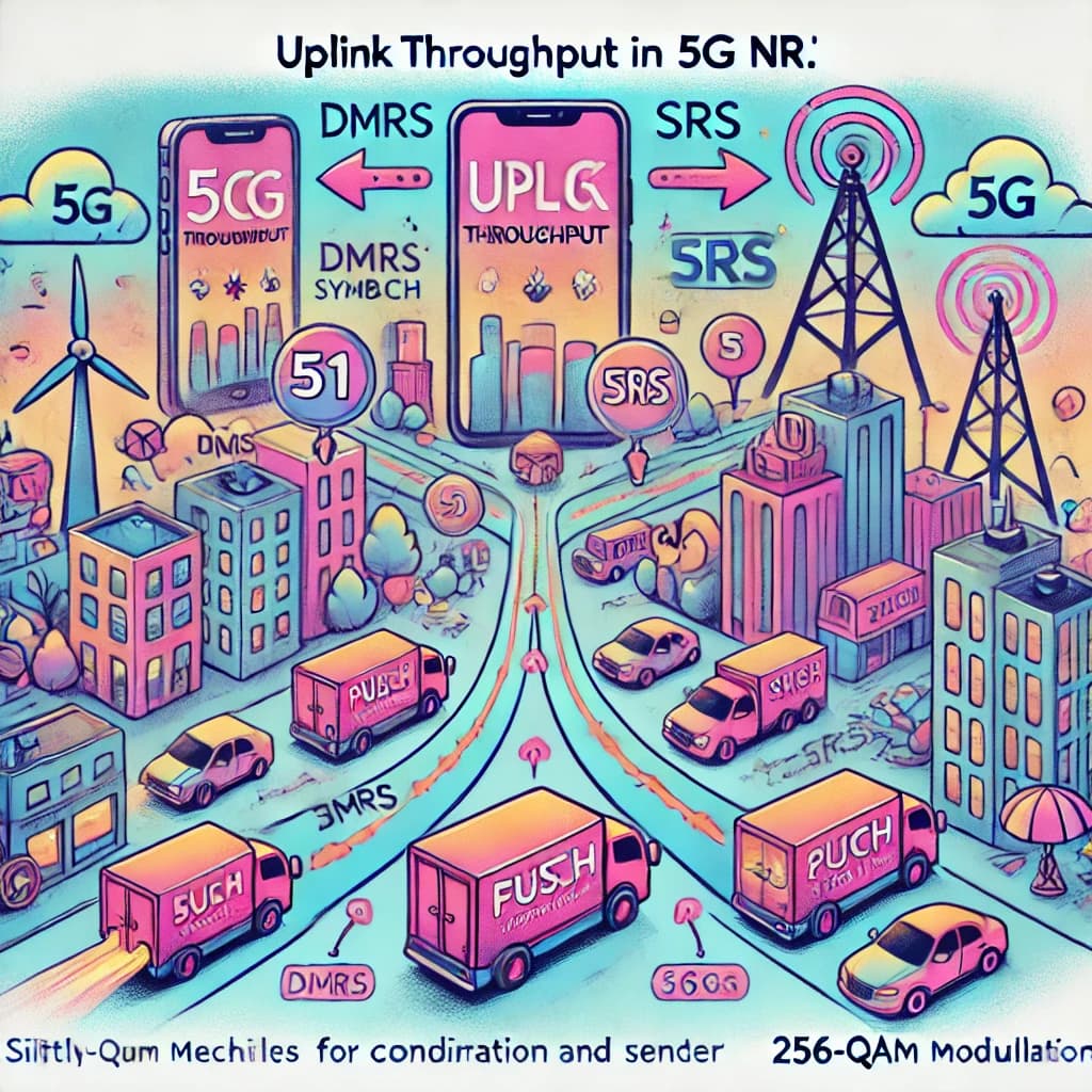
- Search Forum 5G NR Uplink Throughput
Quick Summary
-
Operating Band: Flexible frequency ranges enabling advanced 5G deployments. (Advanced, connected roads for faster, flexible travel.)
-
NR-ARFCN & GSCN: Identify channel center frequencies and synchronization signals. NR-ARFCN offers flexibility with multiple rasters, while GSCN uniquely optimizes SS/PBCH Block alignment for accurate synchronization and resource efficiency. (Advanced orchestras with precise tuning (NR-ARFCN) and alignment (GSCN) for richer, synchronized performances.)
-
Slot Format: Defines how time slots are divided into uplink, downlink, and guard periods, balancing latency, range, and throughput. (Flexible bus schedules adapt to traffic, passenger needs, and routes, ensuring efficient trips and reduced waiting times.)
-
Antenna Solution: Enhances network performance by enabling beamforming and spatial multiplexing. (Advanced adjustable streetlights (antennas) guide traffic efficiently, adapting to complex and high-speed patterns.)
-
Downlink Transmit Power: Ensures compliance with regulatory limits while optimizing coverage and minimizing interference. (Advanced sprinklers (antennas) focus water (power) efficiently, reducing waste and adapting to user needs.)
-
PCI Allocation: Prevents interference by allocating unique PCIs, doubling LTE’s capacity, and ensuring efficient, interference-free 5G operations. (More house numbers (PCIs) reduce mix-ups, with stricter rules ensuring clear, interference-free identification.)
-
Cyclic Prefix: Protects signals from multi-path delay spread with flexible normal and extended guard periods, adapting to diverse deployment needs. (Flexible highways (cyclic prefixes) manage traffic delays efficiently, adapting to short routes or long, busy roads.)
-
CSI Reference Signal: Supports beam management and channel quality measurement with flexible configurations, enhancing accuracy and resource efficiency. (Advanced weather stations (CSI-RS) adapt updates for traffic management, ensuring precise and efficient resource use.)
-
Phase Tracking Reference Signal: Ensures high modulation accuracy and reliability by compensating for phase noise, especially in challenging conditions. (Dynamic clock adjusters (PTRS) ensure precise synchronization, even in challenging conditions, surpassing LTE City’s basic system.)
-
PRACH Planning: Facilitates initial access and synchronization for user equipment (UE) with enhanced flexibility, supporting beamforming, multiple frequency offsets, and diverse formats. (Smart, flexible gates (PRACH) adapt layouts, lanes, and beamforming to manage traffic efficiently and ensure smooth entry.)
-
PRACH Format: Determines the structure of the PRACH signal to accommodate varying cell ranges and mobility requirements - long formats for extended range and short formats for low latency and high mobility. (Flexible bridges (PRACH Formats) connect distant and nearby neighborhoods efficiently, adapting to coverage, latency, and mobility needs.)
-
PRACH Configuration Index: Defines PRACH timing and periodicity, balancing capacity, latency, and overhead for efficient access and synchronization. (Flexible train schedules (PRACH Configuration Index) balance timing, resources, and collisions, ensuring efficient and adaptable arrivals.)
-
Zero Correlation Zone: Prevents interference between PRACH sequences by balancing cell range and collision risk through adjustable cyclic shifts. (Echo-proof halls (Zero Correlation Zones) adapt sizes to balance distance and performances, ensuring interference-free operations.)
-
High-Speed Flag: Optimizes PRACH configurations for varying mobility levels. (Adaptive traffic lights (High-Speed Flag) in 5G City manage vehicles (UEs) based on speed, ensuring smooth and efficient traffic flow.)
-
Root Sequence Index: Defines PRACH preamble sequences to prevent collisions and optimize reuse, ensuring efficient and scalable 5G operations. (Fountains based on area size (Zero Correlation Zone) to prevent crowding and collisions, ensuring efficient.)
-
PRACH Frequency Offset: Determines the placement of PRACH occasions in the frequency domain. (LTE City has fixed spots, while 5G City arranges flexible lanes for efficient, congestion-free parking.)
-
Neighbour Planning: Ensures efficient handovers and mobility by defining inter-cell relationships and avoiding PCI collisions. (Advanced interconnected streets for seamless mobility, LTE-to-NR/NR-to-NR handovers, and PCI collision-free planning.)
-
Cell & BTS Identity Planning: Uniquely identifies cells globally, using MCC, MNC, and NCI, ensuring scalability, flexibility, and support for high-density deployments. (5G City uses advanced unique addresses (NCGI) for efficient, scalable cell identification, handling growth and complexity better than LTE City.)
-
RAN Notification Area Planning: Enables RRC Inactive state for UEs, reducing signaling load by managing mobility within RAN Notification Areas efficiently. (Delivery zones in 5G City (RNAs) reduce constant updates, balancing fewer updates with larger zones and quicker deliveries with smaller ones.)
-
Tracking Area Planning: Manages UE mobility and reduces signaling overhead. (Smarter zones, reducing frequent updates while balancing paging, dynamically adjusting to population and mobility needs.)
-
Throughput Expectations: Estimates uplink and downlink throughputs, considering UE capabilities, Slot Formats, and network variables to optimize performance and planning. (Advanced delivery systems (throughput) optimize personal speeds and overall capacity, balancing resources and prioritizing efficiency.)
-
Downlink Throughput: Calculated per slot, varies with CQI levels, and achieves high performance, often surpassing LTE. (Advanced delivery center (downlink throughput) uses 12 workers (PDSCH symbols) and optimized routes (CQI levels) to deliver faster and more efficiently than LTE City.)
-
Uplink Throughput: Uses 11 PUSCH symbols per slot, slightly lower than downlink throughput. Advanced features like 256-QAM enhance performance, optimizing data transmission efficiency. (Advanced courier service (uplink throughput) efficiently delivers packages with optimized coordination and faster vehicles (256-QAM).)
That’s it. ![]()
-
Continue reading: Roadmap to 5G NR - Dynamic Spectrum Sharing
-
Or back to: Roadmap to 5G NR