Hello Experts,
Why 64TRX (64T64R) is called 16H4V?
I am not able to correlate it.

Hello Experts,
Why 64TRX (64T64R) is called 16H4V?
I am not able to correlate it.

I was trying to visualise it and this is what i could come up with. There are 8 column and each has 2 antenna element so total 16 in Horizontal. 4 rows.

There are 8 columns, so 8x2 = 16 antenna elements per column. So how it is 16H?
What about 4V?
16 horizontal & 4 vertical.
It may be like this as shown in figure:

I am also not able to visualise this.
I mean how it is 16H4V?
Each array with 3 antenna elements.
Are you are telling per array 4 rows?
Is my understanding correct?
In original figure 3 red color dots is confusing…
I have given 1 to 16 number…that is 16H. 4 diff color is 4V.
This is how 3D beamforming happen.
For your 16H and 4V what is the number of csi-rs ports you considered?
As per the diagram, 1 array = 3 elements vertically.
So, there are 4 arrays vertically.
So 4V is representing this? I don’t understand from how they got 16H.
4x8 = 32 arrays x each 3 atenna elements x each with 2 polarisation = 192

I am not sure, looking difficult to accommodate in 12 csi-rs ports.
Yes, I think your understanding was corrrect.
I have changed my view.
This is really interesting.
Experts please give final view.
Max number of csi-rs ports is 32.
That can be accomodated with those configs:
Which one is your case of 16H4V?
Yes, that I understood.
1 column = 4 Arrays = 4x3= 12 AE (1 array contains 3 AE).
There are 8 columns.
Total AE= 8x12 =96 AE = 96x2 pol= 192.
Main confusion is the visualization of 16H4V.
So I think 4x4 32 csi-rs ports can be used as per my understanding.
What is your thought?

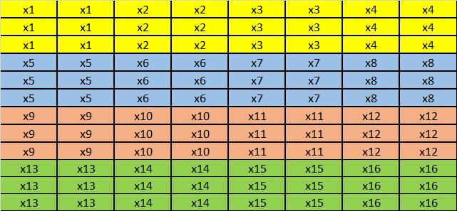
So here x1…x16 is one X, so 4x4 is perfect fit in 3D beamforming.
x1 contains 12 AE so 16x12 = 192 AE.
I think 16H4V is mistake or typo.

Visualise my figure with this.
What is your view with this.
In that diagram, there are 12 rows and 8 columns.
How many antenna elements are being used for creating 1 horizontal beam?
All of the 12 x 8 = 96 antenna elements.
Defininately, 64T64R can only be 8H4V (why? 4TRX in vertifical x 8TRX in horizontal x 2 (dual-polarized)=64T64R). If it is 16H4V then it’s 128TRX which can not be configured from the original diagram (antenna panel) since only 8 columns exist.
Another thing is, antenna element is referring to 2 polarized as 1 AE (then it’s 843=96 AE) or it’s referring to only one polarized antenna (+45 or -45 degree), then it comes to 192 AE. I guess 192 AE makes more sense, as each AE = physical antenna. And each AE (physical antenna) out of 192 has the same precoding (amplitude and phase) if it’s from the same antenna subarray with the same polarization.
About CSI-RS port mapping, 3GPP defines maximum 32 ports in CSI-RS based codebook feedback. And the purpose of CSI-RS is, each subarray (one beam) needs to be associated with one CSI-RS resource (2 CSI-RS port actually due to 2 polarized), so we have 32 beams (32 sub arrays) then we need 64 CSI resources for UE to measure. Since maximum 3GPP defines 32 CSI-RS resource(port), corresponding to 32 RE, we can have two beams sharing the same CSI-RS port.
Per current subarray structure, we have N1=8 (8 horizontal beams) and N2=4 (4 vertical beams), so per 3GPP CSI port table, there is no (8,4) but only (8,2). So either we should reuse the resource of two vertical beams per (8,2), or we reuse the resource of two horizontal beams per (4,4).
But I don’t know how to map in above situation. Hope someone can explain further.